This thread has been locked.

If you have a related question, please click the "Ask a related question" button in the top right corner. The newly created question will be automatically linked to this question.

LMP7701: Slew-rate limited for a 0.1 V/us input?

Part Number: LMP7701
Other Parts Discussed in Thread: TINA-TI

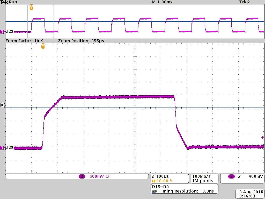
Hi, I'm using an LMP7701 as a transimpedance amplifier with 249-kohm gain.  When I apply a signal to the non-inverting terminal, I expect to see it on the inverting terminal, via feedback action--this method is often used in electrochemistry.   But with this circuit, when I apply a square wave with 10-µs rise/fall times to the non-inverting terminal, I see segmented rising and falling edges on the inverting terminal--the signal tracks the input nicely for about 0.6 V, but then ramps over.   I'm guessing this a slew rate limitation, but the applied dV/dt is only 0.1 V/µs, whereas the typical slew rate for the LMP7701 is about 1 V/µs (at Av = +1).

Supply voltages are ±6 V.  The load on the transimpedance amp is 20 kohm in parallel with the input capacitance of another LMP7701.   There's a 20-pF cap in parallel with the 249-kohm feedback resistor.

Thanks for any advice!  --Chris

  • Chris,

    A transimpedance amplifier converts an input current (and NOT input voltage) applied to an inverting input to a voltage at the output. But the way you describe it is nothing else but a follower with a feedback resistor so the output should simply follow input (no gain).  The change to voltage slope at the output is most likely caused by slew boost circuitry.  Please show your schematic - a picture is worth thousands words.

  • Hi Chris,

    in the TINA-TI simulation this only happens, when you have a capacitance of more than 1nF connected from the inverting input of LMP7701 to signal ground.

    This underlines how important it is to present a full schematic, as Marek already mentioned...

    Kai
  • Thanks for the replies. Sorry I didn't attach a schematic. In any case, the problem is resolved. I determined that the transimpedance amp was railed by the fast rising and falling edges of the applied signal, due to high gain and a fair amount of capacitance on the inverting terminal.