This thread has been locked.

If you have a related question, please click the "Ask a related question" button in the top right corner. The newly created question will be automatically linked to this question.

TINA/Spice/LMP2012QML-SP: Input common mode range when powered by 3.3V and Pspice model.

Part Number: LMP2012QML-SP
Other Parts Discussed in Thread: TINA-TI, LMP2011, LMP2012, OPA191, LMP2021, , LMP2012QML

Tool/software: TINA-TI or Spice Models

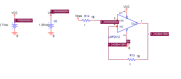
I does not seem the LMP2011 Pspice model is valid as simulation does not agree with datasheet. 

The datasheet specs gain and phase margins at 2.7V with Vcm=1.35V.  However opamp model fails to simulate properly at this bias voltage see below. (output is not same as input in voltage follower unity gain config and if I evaluate gain and phase margins at this bias I get garbage with gain down to -160dB at 1Hz )

If previous advice that device cannot be operated above Vcm=VDD-1.8V then how can datasheet specify phase and again margins there.

We also have tested devices at 3.3V supply at Vcm=1.65V that operate properly but simulation model also fails there.  

If Vcm is made lower (<<VDD/2) the simulation model works but phase margin is somehwhat worse than spec. More like 8.8dB,42deg. 

Do you have a better Pspice model that agrees better with datasheet and actual parts?

Mike

  • Hello Mike,

    I do agree that the LMP2012 model does not accurately reflect the silicon in this test case. This is an older model from National on an architecture that is known to have some issues. We are in the process of updating our older models to a new and significantly improved architecture, but unfortunately the LMP2012 has not been done yet.

    In the meantime, why don't you try simulating with the OPA191 instead? It's on our updated architecture, and from a small-signal AC analysis perspective it's very similar to the LMP2012 with Aol = 134 dB, GBW = 2.5 MHz and phase margin = approximately 60°. While the real OPA191 would not operate at Vs = +2.7V, the model will and should have no input common-mode limitations.

    Best regards,

    Ian Williams
    Applications Engineer/SPICE Model Developer
    Precision Amplifiers

  • Hi Ian,
    I am trying to show worst case gain and phase margin in a design and not sure using a model for different device with different behavior would be accepted. Thanks for acknowledging the LMP2011 model issues. There does not appear there is much else TI can do for me at this time.
    Thanks,
    Mike
  • Mike,

    Actually, LMP2021 macro-model correctly shows the problem with Vcm=1.35V when operating on 2.7V supply but you are overlooking a disclaimer at the top of the page - Unless otherwise specified (see below).   Most of the specs are specified by default with Vcm=Vout=Vs/2 (mid-supply) unless the part cannot operate linearly under such conditions and that's the reason for the Test Condition column that overwrites the default conditions at the top of the page.  The linear input common-mode voltage range of LMP2021 irrespective of the supply voltage is (V-)-0.3V<Vcm<(V+)-1.8V, which translates into -0.3V to 0.9V for Vs=2.7V single supply but you are trying to force it to work at Vcm= (V+)-1.35V;  however, I do agree that the Table 6.7 AC Characteristics for 2.7V was improperly copied over from Table 6.9

    At Vs=3.3V supply and Vcm=1.65V, you are very close to meeting Vcm<(V+)-1.8V specified range for the linear operation; under such conditions most actual parts will operate properly but because of the process variation resulting in the range varying few hundred milliovolts from one wafer lot to the next, and the fact that the circuit may seem to work fine as far as Vos with Vcm=1.65V, however, may not meet other datasheet specifications like bandwidth, slew rate, noise, etc., we would still show in simulation Vos to get out of limit in order to flag the potential problem to the end user.

    All in all, macro-model properly show where LMP2021 may have a problem operating properly and you should not use the part with Vcm>(V+)-1.8V 

  • Merek,

    It is true the CMRR spec is specifed at VCM<0.9V above but Vos  and (Gain and phase margins in another table ) are specified at Vcm=1.35V.  In the Pspice simulation using the LMP2011 model Vos appears to be 0.104V instead of 60uV (actually model is cutoff and not working at Vcm=1.35V).  I have already increase the supply voltage in the actual application but unfortunately open loop Gain and phase in model do not match datasheet well enough to use for proving stability margins. I understand it is a model and will not duplicate every specification under all conditions.

    Thanks,

    Mike

  • I know this is a long shot but is there any data showing unit gain and phase margins post radiation or life testing. The radiation reports do not offer anything likely because it is not an SMD 5962-06206 tested parameter.

    Thanks,
    Mike
  • Yes, you have a point about Vos being erroniously shown with Vcm=1.35V on 2.7V supply; since the input stage does NOT work linearly with Vcm>(V+)-1.8V, all specs (including Vos, AOL, etc.) under such conditions are shown incorrectly but the macro-model correctly flags the potential problem.  However, if the Vcm is close to meeting the Vcm specified range (e.g. Vcm=~(V+)-1.6V) most units will work properly even though the macro-model will show a problem.

  • Mike,
    We do not perform radiation tests on our parts but Space & High Reliability group supporting Enhanced Products (EP part suffix), High Temp products (175C to 210C), Space products (rad-hard, rad tolerant, QMLV, QMLQ), and bare die (-DIE part #’s), may have such data - see link below:
    e2e.ti.com/.../935

    Having said that, our products are tested for parametric shifts during life test (long-term shift) and the maximum shift of the parameters like AOL is 6dB while bandwidth may move up to +/-10% resulting in few degrees change in the phase margin.

  • For the space grade products, such as the LMP2012QML-SP, the radiation reports are in the Technical documents tab of the product folder on ti.com.

    Gain drift through 50 krad (the TID rating for this part) is shown in the report.

    www.ti.com/.../technicaldocuments
  • The radiation data raises more questions. The LMP2011 Pspice model has open loop gain of 98db. The LMP2012 radiation report is showing open loop gains start around -140dB. Why the negative sign in the gain data? Ignoring the negative sign why is gain indicated so much higher than LMP2011 model.
    Are the die/performance the same for LMP2011 and LMP2012QML?