This thread has been locked.

If you have a related question, please click the "Ask a related question" button in the top right corner. The newly created question will be automatically linked to this question.

OPA191: Negative voltage input threshold.

Part Number: OPA191
Other Parts Discussed in Thread: TINA-TI

Hi,

I am just about to use the OPA191IDBVT op-amp as a non-inverting amplifier, with the op-amp being powered from +5V and 0V.

My question is if the + input on the non-inverting amplifier drops below 0V, say 200mV, will the input protection diodes on this op-amp prevent the op-amp destroying itself, or should i put a BAT54 on the input between the + input and the 0V rail?

Look forward to your reply.

Thanks,

Rocketman46

  • Hi Rocketman,

    are you sure that's no more than 0.2V? In this case no input current will flow and the OPAmp is safe. But if it's more, then I would limit the input current by the help of a current limiting resistor to <10mA or even less. See the absolute maximum ratings of datasheet.

    Kai
  • Hi Kai,

    Thanks for your reply.

    Would you still fit the BAT54?  Am i correct in thinking it will stop the input dropping below 0V?

    Thanks,

    Rocketman46

  • Hi Rocketman,

    the BAT54 will clamp the input voltage at up to 320mV for a diode current of 1mA, at up to 400mV for a diode current of 10mA and at up to 800mV for a diode current of 100mA. So, without a current limiting the BAT54 might not be of any help.

    The BAT54 can help to shunt the biggest portion of input current arround the OPA191. But you might still need a current limiting resistor.

    The disadvantage of the Schottky diode BAT54 is, that it shows a huge leakage current and can tremendeously increase the input bias current or, by other words, decrease the input impedance of your circuit. So, a low leakage diode like the BAV199 might be better suited.

    Can you give some more details about your circuit?

    Kai
  • Hi,

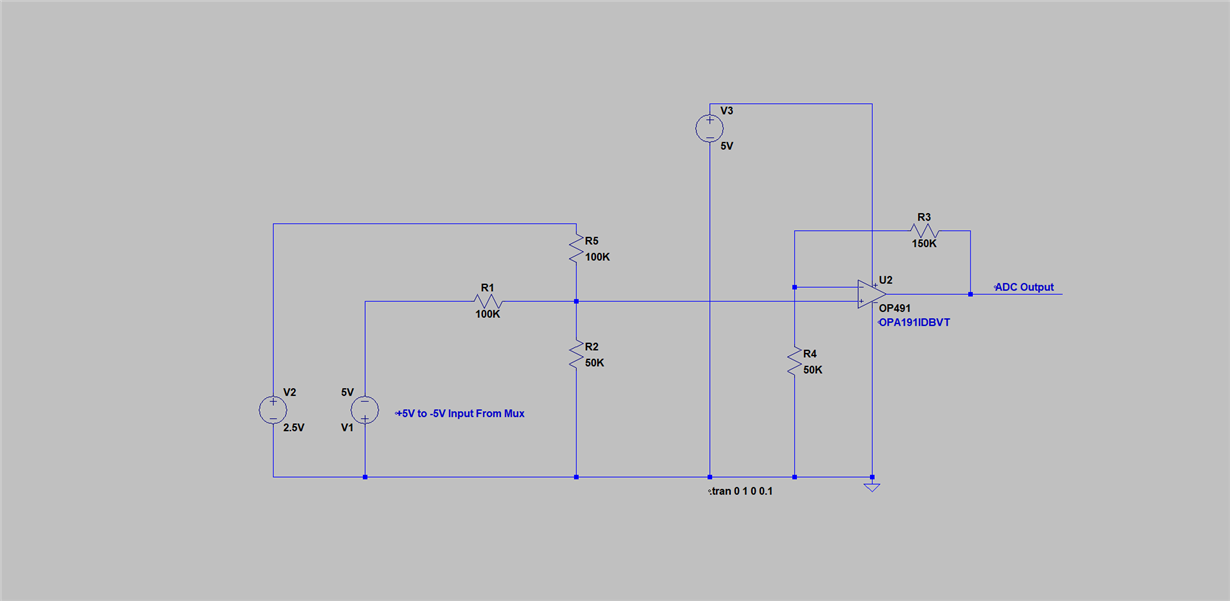
    Essentially I want to feed +5V to -5V from a mux into an ADC on a micro.  Below is the circuit and Input and Output voltages from the circuit.  The only glitch is when the input is 0V to -5V and this voltage is feed into the + input on the op-amp.

    * V1 +5V,      ADC_Vout +5V

    * V1 +2.5V,   ADC_Vout +5V

    * V1 0V,        ADC_Vout  2.5V

    * V1 -2.5V,    ADC_Vout  0V

    * V1 -5V,       ADC_Vout  0V

    Thanks,

    Rocketman46

  • Hi Rocketman,

    I think the 100k resistors are protecting the inputs enough. But you should keep in mind that leaving the common mode input voltage range can cause other trouble.

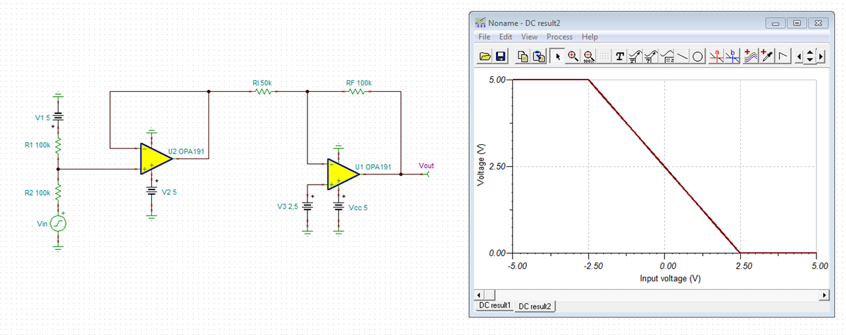
    A circuit which would avoid leaving the common mode input voltage range is shown below:

    You would still need to invert the signal in the software.

    Kai

  • Here's the TINA-TI file:

    rocketman.TSC

    Kai

  • Hi Kai,

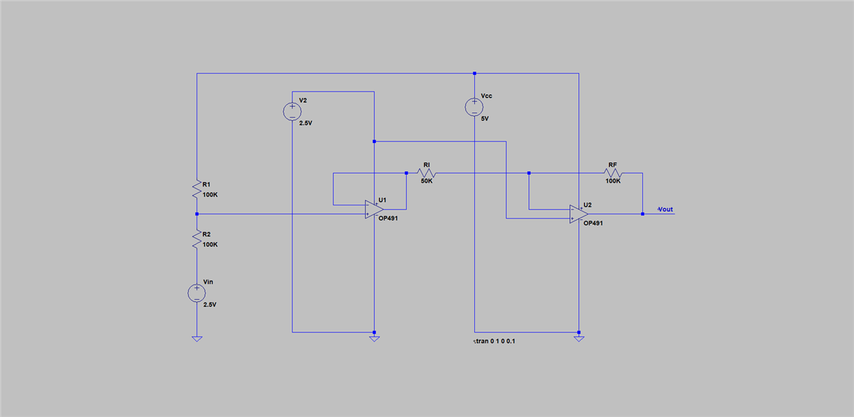
    I cannot get the same results as you.  Is this because I am using OP491 op-amps because my spice package does not use the OPA191.  Is my circuit different to yours?

    Thanks,

    Rocketman46

  • All sorted now, I made a circuit mistake.

    Thanks for your help.

    Regards,

    Rocektman46
  • Hello Rocketman46,

    OPA191 datasheet Figure 60. shows the Equivalent Internal ESD Circuitry Relative to a Typical Circuit Application. It can be seen that there are ESD protection diodes from each input, to each supply line. The lower ESD diode can be forward biased if the non-inverting input is driven to about 500 mV or more, below ground. That level of voltage will turn the ESD diode on, but the diode will then clamp the input voltage protecting the op amp input circuit. The main criterial to watch is that the input current through the diode doesn't exceed the 10 mA maximum rating.

    The OPA191 input is robust enough with the ESD protection diode that an external diode should not be required. Adding an external diode can add leakage current to the input circuit that makes the input current much higher than when the diode isn't used.

    Regards, Thomas

    Precision Amplifiers Applications Engineering

  • Hi Kia,

    I have modelled this circuit and I have one last question.

    * If I use the full circuit the output goes from 5V to 0V.

    * If I use the front half of the circuit R1, R2, and U2 the output goes from 0V to 5V

    Can I not just use the front half of the circuit, the two resistors and the unity gain buffer? I am trying to understand the full circuit and I don't understand the reasoning for the second half of the circuit.

    Thanks,

    Rocketman46
  • Hi Rocketman,

    in your circuit is a mistake. The supply voltage of the first OPAmp shall be 5V not 2.5V. The label "V2 5" means: Voltage source V2 with 5V. It does not mean 2.5V.

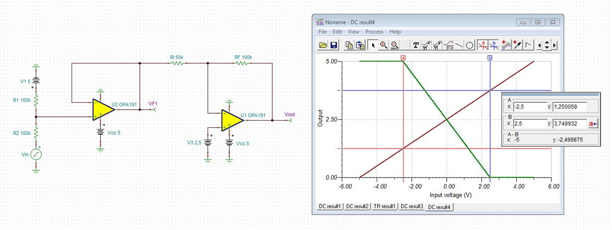
    The first stage eliminates the negative input voltages and transforms the range of -5V...+5V into the range of 0V...+5V. The second stage sets the gain or scaling in order to transform the input voltage range of -2.5V...+2.5V into the output voltage range of +5V...0V. Without the second stage the input voltage range of -2.5V...+2.5V would be transformed into the output voltage range of +1,25V...+3,75V:

    rocketman1.TSC

    Kai

  • Hi Rocketman,

    does this answer your question?

    Kai
  • Hi,

    Yes excellently answered thank you.

    Regards,

    Rocketman46