This thread has been locked.

If you have a related question, please click the "Ask a related question" button in the top right corner. The newly created question will be automatically linked to this question.

TL084: AC Mains voltage sensing accuracy

Part Number: TL084
Other Parts Discussed in Thread: OPA4188, TIDA-01606

Hi,

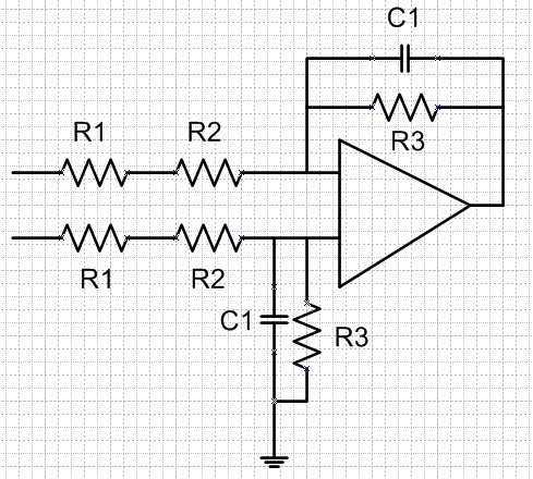
I am now use TL084 for ac mains voltage sensing. The voltage sensing circuit is as below.

My question is :

1. If I increase the resistance of R1, and keep the same filter frequency and gain, the accuracy will increase? 

2. If I use OPA4188 replace TL084, the accuracy will increase?

3. Any suggestions for the design? 

  • Hello,

    Increasing the resistance of R1 will not increase the accuracy of the circuit. If you increase R1 you will also need to increase R3 to keep the gain the same and reduce C1 to keep the filter cut off frequency the same. Increasing R1 and R3 will introduce more noise into the system circuit. If the op amp you were using had higher input bias current (like a typical bipolar op amp) you would also decrease the accuracy because the error due to the interaction of the resistors and the input bias current of the op amp.

    Using the OPA4188 would improve the accuracy. The offset voltage of the TL084 is 3mV (typical) whereas the OPA4188 offset voltage is 6uV (typical). This is a 500x improvement just due to offset voltage.

    I recommend you take a look at our Analog Engineers Circuit Cookbook for help in designing your circuit. Within the cookbook there is a Difference Amplifier (Subtractor) Circuit that provides design notes and a step by step process on how to design the circuit.

    I also recommend watching out TI Precision Lab videos on op amps. The videos discuss everything from sources of errors in op amps (Vos and Ib) to stability of an op amp.

    Thank you,

    Tim Claycomb

  • Hi Dragon,

    how do you want to measure the mains voltage with this circuit?

    Kai
  • Hello,

    Thanks for the reply. I have seen the similar circuit in  TIDA-01606. But I am confused that why using so large resistance R1=1M* 3pcs=3M ohm. I use <1Mohm in my design, but I am interested that why the application use such high resistance. 

    I use voltage divider+ differential circuit to OP-amp, and then fed the output to DSP. And what I want to do is increase the sensing accuracy via adjusting Resistor value and select a suitable OP-amp. 

  • Hi Dragon.

    mains voltage is contaminated with surges and transients of up to 6kV. A single resistor cannot withstand this extreme overvoltages. That's why a series circuit of three or more resistors is usually used.

    Have a look into the datasheet of your 1M resistors to see what overvoltages they can withstand!!

    For mains voltage stuff I like to take the VR25 and VR37.

    Kai
  • Hello,

    Kai is correct. This is a common technique in many high voltage applications.

    The article "Considerations for Higher Voltage Measurements" written by a colleague of mine discusses some other considerations you might want to consider when sensing high voltage.

    Thanks,

    Tim Claycomb

  • Hi Kai:

    Thanks for the reply. Actually I use 3 pcs 301K ohm in series. And I am interested on : If the gain and cut-off frequency is the same, what's the difference between using 3*1M ohm & 3*301K ohm? 

  • Hello,

    Using 3*1Mohm resistors will not produce the same gain as using 3*301kohm resistors for R1. Using 3*1Mohm resistors creates an equivalent resistance of 3Mohm whereas using 3*301kohm creates an equivalent resistance of 903kohm.

    The transfer function of the circuit you provided is R3/(R1+R2), therefore by changing the equivalent resistance of R1 changes the gain of your circuit. The only way the gain will be the same is if you change the R3 resistor value.

    If you change the resistor value of R3 to keep the gain the same then the main difference would be an increase in noise and offset voltage due to the interact of Input Bias Current and the resistor.

    I recommend watching our TI Precision Lab videos on Noise and Vos and Ib for more information. I think all of your questions will be answered in these videos.

    Thank you,

    Tim Claycomb

  • Hi Dragon,

    the resistors' job in the TIDA-01606 is more than just to withstand surges and transients. They do also "isolate" the two grounds PGND and GND from each other. I guess the developers had good reasons to take 1M resistors.

    Kai
  • Hi Dragon,

    are there any further questions?

    Kai