This thread has been locked.

If you have a related question, please click the "Ask a related question" button in the top right corner. The newly created question will be automatically linked to this question.

OPAMP calculation for sensing output current

Other Parts Discussed in Thread: LM324, LM358, TLV9001

Hi Team,

   Today I participated TI technical roadshow I’ve heard that opamp’s offset voltage would influence the accuracy. I’m not that familiar with the calculation. I would like to give you my parameters to check whether it     work or not.

  We use a current transformer and LM324 for our MCU to calculate our output current (AC).

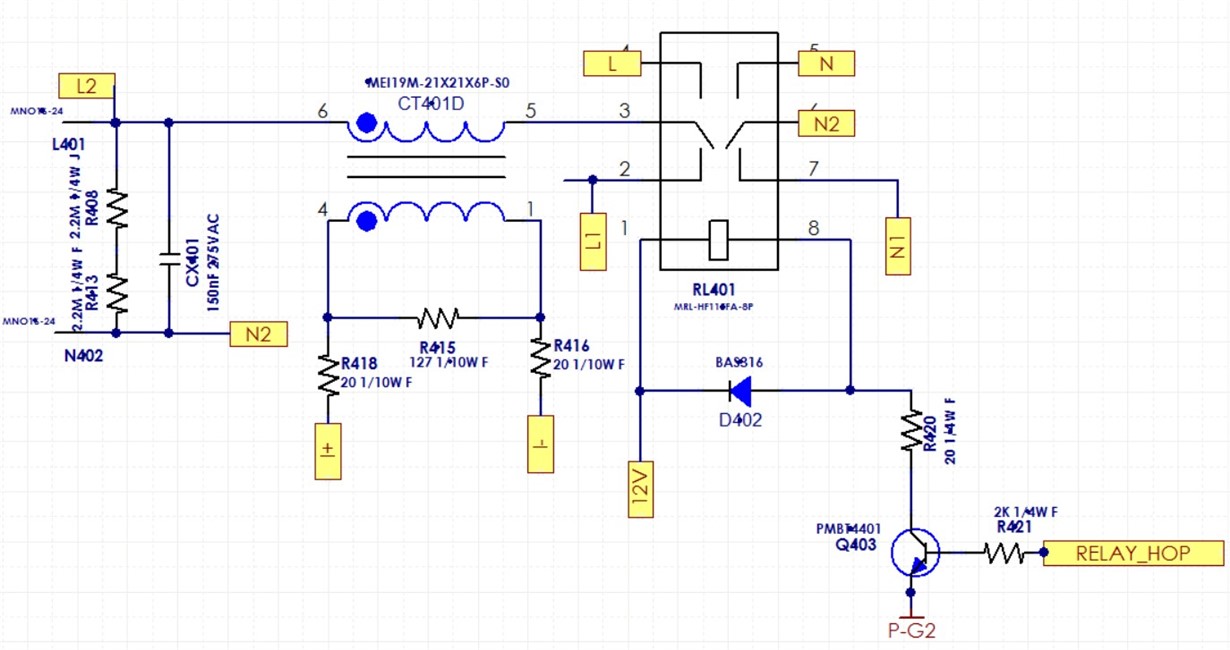
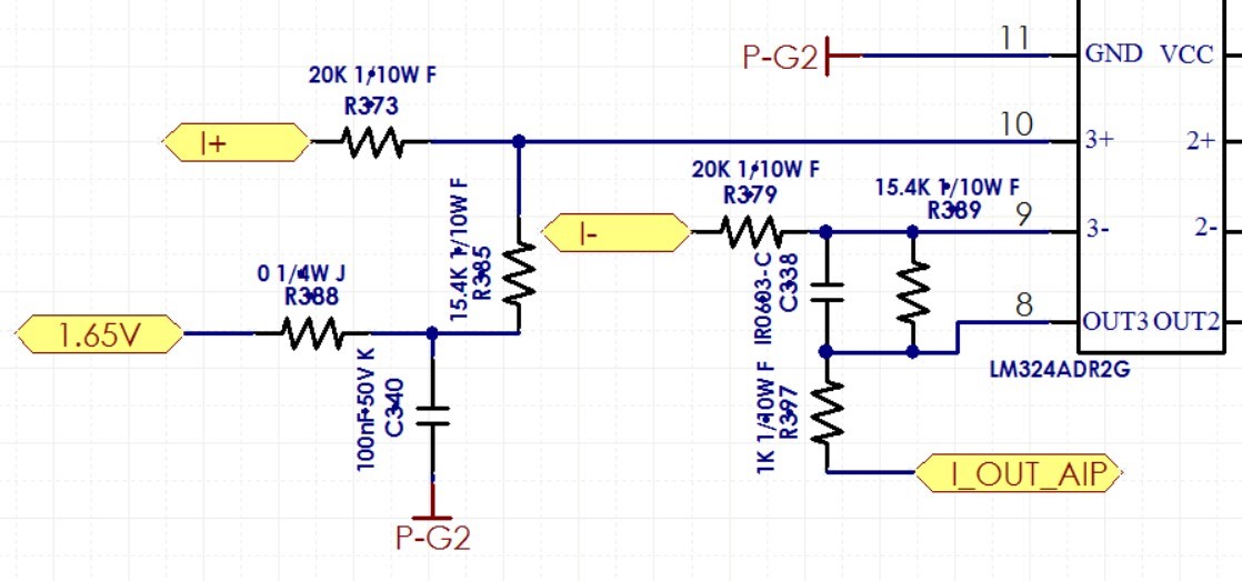
  The circuit is shown as below.

  L2 and N2 are connected to our output. CT401’s terminal 4-1 is 1000 turns and terminal 6-5 is 1 turn.

  I+ and I- are connected to LM324 to generate a signal for MCU(STM32F030C8T6TR) to calculate the output current.

 Our current accuracy criteria is 3%, is there any problem with our parameters?

 Or we can use MCU to shift the reference voltage to avoid OPAMP’s offset voltage to influence our current accuracy.

 Deeply appreciate your patience and response.

Best regards

Mitch 


  • Hi Mitch,

    The easiest way to think about this is when there is no current present in the system. In that case, the voltage on the output is going to be:

    V_noload = Gain*Vos

    This means that if your input current level creates a voltage that is near the magnitude of your V_noload, then you'll have high error. Depending on your system's tolerance, the lowest current you can accurately sense will change. For instance, if you were okay with 10% error, you'd want your smallest current to generate a voltage that is 10x larger than V_noload because your output voltage will be V_noload+V_load.

    Can you tell me what your minimum and maximum currents are?

    Thanks,
    Paul
  • Hi Paul,

    Deeply appreciate your prompt reply.

    Our application is UPS so our specs don't have minimum current.

    ( Our firmware engineer say the minimum sensing current is about 2.05mA, I'm not sure whether this could help. )

    The maximum current is 3A(rms, output current is AC).

    Thank you.

    Best regards
    Mitch
  • Hi Mitch,

    With the 1:1000 current transformer, an input current of 3A will give a current on the secondary side of 3mA, leading to a voltage across the 127-ohm sense resistor of 381mV.

    The circuit as shown has a gain of 15.4k/20k = 0.77 so the output voltage will be 381mV*0.77 = 293mV for the maximum current case.

    The worst case offset for the LM358 is 7mV so in a no-current case, the output voltage will be 5.4mV, representing the error in the circuit. In the maximum current case, your error is (293+5.4)/293 - 1 = 2%

    This circuit can sense as low as 54mV/0.77/127Ohm*1000 = 0.55A with 10% error. Any currents less than that will have higher error.

    I hope I got the current transformer details and circuit details correct, let know if you see any errors or if I misunderstood something. To increase your accuracy, the best thing to do would be to choose a device with a lower offset voltage. Devices like the TLV9001 are newer parts that have much better offset voltage specs and will perform this task better than the LM358.

    Best,
    Paul

  • Hi Paul,

    Many thanks for your clear and detailed explanation.

    (BTW, I’m using LM324 instead of LM358, but I think the parameters would be the same)

    I only have two questions left.

    1. The calculation you mentioned “ 54mV/0.77/127Ohm*1000 = 0.55A with 10% error”
    I’m not quite sure why is 54mV instead of 5.4mV and why is 10% error.

    2. If we use MCU to shift the reference voltage to avoid OPAMP’s offset voltage to influence our current accuracy.
    Is there any side effects?
    Ambient temperature concerned or something else?

    Thank you

    Best regards
    Mitch
  • Apologies on the lack of clarity around my 10% error example, let me clarify:

    If we wanted to find out what input current level has 10% error we would do it this way:

    Output Error Voltage due to offset = 5.4mV

    Output Voltage where error is 10% = 5.4mV/0.1 = 54mV

    Total Output Voltage = Output Offset Voltage Error + Output Current Shunt Voltage = 5.4mV + 54mV = 59.4mV

    Error = (Real Value/Desired Value)-1 = 59.4mV/54mV - 1 = 10%

    From here, we can back calculate the input current level that causes an output voltage of 54mV:

    Input Voltage = Output Voltage/Gain = 54mV/0.77 = 70.13mV

    Input Current (Transformer Secondary) = Voltage/Rshunt = 70.13mV/127Ohms = 0.552 mA

    Input Current (Transformer Primary) = Secondary Current * 1000 = 0.55A

    Regarding your second question on shifting the reference voltage, that's not going to eliminate the error from the offset voltage because it will just add to whatever your reference voltage is and still show up on the output. For example, if you shift your reference voltage down to say 1.60V, now your no-current condition should ideally give you 1.60V on the output. But the offset will show up and cause the value to be something other than 1.60V. The other issue with adjusting the reference is that offset voltage for each op-amp is going to be different. Some will negative, others positive, some small, some large so unless you intend to adjust for each system, it's not really feasible. More practical is to calibrate your systems after they are assembled. 

    Best,

    Paul