This thread has been locked.

If you have a related question, please click the "Ask a related question" button in the top right corner. The newly created question will be automatically linked to this question.

TINA/Spice/OPA365-Q1: phase margin with driving capacitive load

Part Number: OPA365-Q1
Other Parts Discussed in Thread: TINA-TI, OPA365

Tool/software: TINA-TI or Spice Models

Dear all,

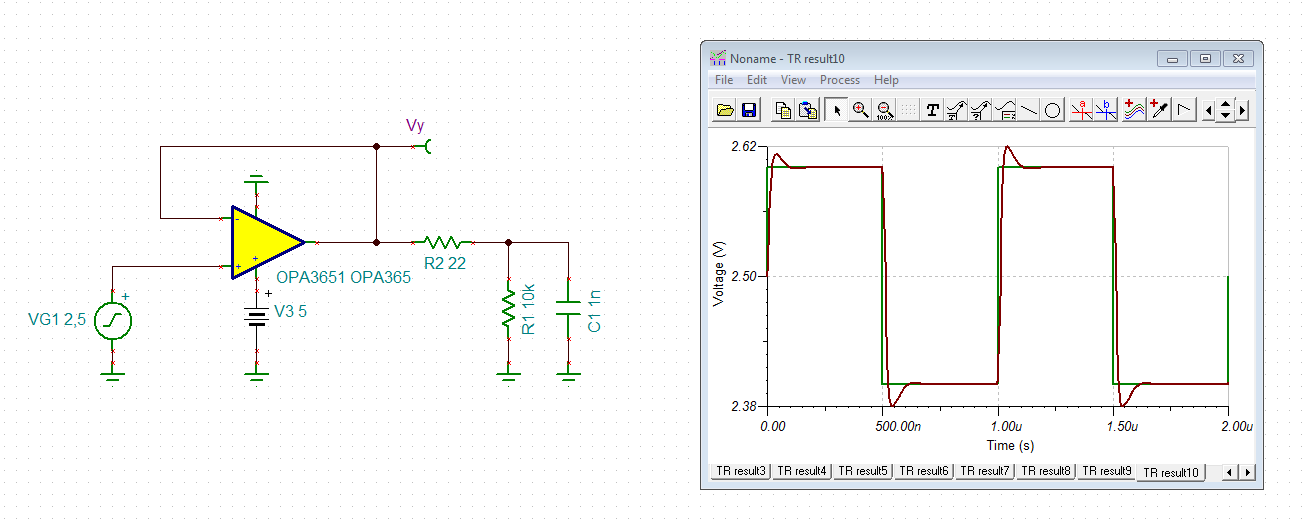
I simulated OPA365's phase margin with driving capacitive load (1nF) by TINA-TI.

But the phase margin was not so good. I know that we should have over 45 degree margin.

Please check following file that TINA result and TINA project file.

OPA365Q1 phase margin_result.pdf

OPA365Q1 phase margin project.TSC

Could you teach me how to think about phase margin and how to control phase margin with driving capacitive load?

I referred to '9.1.1 Capacitive Loads' at data sheet, so I added series resistor at output line.

Now, I plan to input signal from hundreds [kHz] to several [MHz].

Best regards,

  • Hi Takao,

    apart from the phase margin issue, I think you should overthink the circuit. A 1n load capacitance presents a load impedance of 160R at 1MHz and 16R at 10MHz. This looks almost like a short circuit.

    Kai
  • Hi Takao,

    The way I think about cap load drive ability is by graphing closed loop output impedance against the load impedance. A capative bode plot will be -20dB/dec and and an amplifier will usually look "inductive" at +20dB/dec. If these two intersect, they will form an LC tank and oscillate. You can then easily determine an appropriate isolation resistance to prevent them from intersecting. "Gain" below is in units of ohms.

    Best regards,

    Sean

  • Hi Sean,

    Thank you for your answer!

    Could you give me your simulation(.TSC) file? I want to check your simulation settings.

    And, please reply questions below?

    QUESTION 1; Is my understanding correct?

     Should we choose resistance value at the closed loop output impedance curve's top point? 

    QUESTION 2; capacitive load

     At your circuit, it looks that there are not capacitive loads at output.

     Isn't it neccessary to add capacitive loads when we check isolation resistor?

    Best regards,

    Takao Yamamoto

  • Hi Sean,

    Sorry, I have one more question.

    QUESTION 3; phase margin
    After we decide isolation resistor, should we check phase margin with resistor decided?

    Best regards,
  • Hi Takao,

    why not increasing the isolation resistor from 10R to 22R?

    takao.TSC

    Kai

  • Hi Takao,

    1. Yes, that is my intention with this graphical example. But as Kai has demonstrated, this is a very conservative Riso, and can be decreased if some overshoot is acceptable. My point was to prevent "Zload" from becoming equal in magnitude to "Zo" (closed loop output impedance) over frequency. However, all that you really need to do is prevent the load from looking capacitive at the frequency where Zload=Zo.  This is because Zo looks inductive, and an inductor connected to a capacitor will oscillate while an inductor connected to a resistor will not oscillate. A resistor set to either prevent an intersection or which makes this intersection 20dB/decade is acceptable.

    2. I am measuring the Zo (inductor) and the Zload (capacitor) separately and graphing them against each other. I can then see if there will be resonance when I connect them together.

    ZoCalc.TSCLoadCalc.TSC

    3. Riso should strictly increase the phase margin, a bigger concern may be reduction in output swing.

    Best regards,

    Sean

  • >Hi Sean,

    Thank you for your support.
    I can check your file, but could you teach me how to convert the vertical axis label from gain to resistance?
    And I understand that this circuit will not oscillate if we use over 62 ohm resistor, is this correct?
    (I simulated phase margin by my project file above, however the phase margin is only 5.81 degree.)

    Finally, this may be entry-level question, do you have documents that explain the relationship of 'Zload' and 'Zo'?
    It is difficult for me to understand the oscillation mechanism from Gain curve.

    >Hi kai,
    Thank you for your support, too.
    In this case, we don't care about overshoot so much.
    We focus on how to drive 1nF capacitance circuit without oscillation.

    Best regards,
    Takao Yamamoto
  • Hi Takao,

    TINA-TI displays the quotient Vout / Iout in dB on the y-axis, which is "Zo" / "IG1" here. So, 0dB reads 1R, 20dB reads 10R, 40dB reads 100R and so on.

    Overshot is a measure of stability! Have a look at this video:

    training.ti.com/ti-precision-labs-op-amps-stability-4

    So, if you want to avoid oscilation, take better an isolation resistor of 22R and not 10R.

    Kai