This thread has been locked.

If you have a related question, please click the "Ask a related question" button in the top right corner. The newly created question will be automatically linked to this question.

INA260: Is the on-chip shunt isolated from the rest of the device?

Part Number: INA260
Other Parts Discussed in Thread: INA3221, INA190

Team,

-Is the shunt isolated from the rest of the device?

An isolated DCDC is used in the project. The goal is to be able to monitor the DCDC input current while the INA260 is being supplied by the DCDC output.
-Is it possible? Could you please suggest a mechanism to do that?

Thanks in advance,

Anthony

  • Hello AnBer,

    Thank you for reaching out on the forum.  Could you tell us a little more about your DC DC converter (input, output voltages, and expected current levels, and what general topology are your customer is using).   The INA260 shunt is not isolated.  Here are a few reference designs that may have a possible method to help your customer achieve their objective: TIDA-00313TIDA-01590,   TIDA-01608.  Aside from the isolated reference designs, here is also a non-isolated option that may be worth looking at.

  • Hello Patrick,

    I'm the end customer.
    We use Gaia converter MGDBI-04-IC. Input voltage range is 18-36V (typical 24V), output voltage is +/-5V.
    Output current requirement is around 200mA.

    Regards,

    Pierre
  • Hi Pierre,

    can you show a schematic?

    Kai
  • DC_DC.pdfHi,

    Here it is.

    Pierre

  • Hello Pierre,

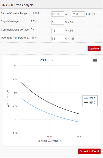
    At startup I would expect that there will be a brief duration in which the bus voltage to the INA260 input will be >18V, while the INA260 supply will be below 2.7V.  This will not destroy the INA260, however you will not be able to get any meaningful output from INA260 as the supply is below the minimum required value and I suspect your I2C lines will also not be adequately pulled up to their necessary levels.  If you do not need measurements during this initial startup period, then I believe you could use this device.  However, because you are trying to measure in the milliamp range and this device has a rather large voltage offset, the measurement could have a relatively high percent of error (as shown in figure below).

  • Hello AnBer, Pierre,

    I have not received any followup from you all, therefore I presume you are proceeding with the INA260 or have found an alternative device that fits your needs. As such, I am closing this thread. However, if you do need more support on this topic, please reply below to reopen the thread or start a new thread for a new topic.
  • Hi Patrick,

    Sorry for my late answsers.

    Startup is not an issue. The system has to boot before it starts polling the INA260 register. Supplies will be stable then.

    The other point, error, is more a problem. 200mA power requirements are at the output.
    Converted to input, this translates to 83 mA. In that case this error will be around 10%.
    As our system will be located in a closed cabinet, where usually temperature is between 50 to 60°C, it will be even worse than 10%.

    I see two options: use a different device with an external shunt or simply use INA260 to monitor the DC/DC output current and accept 5-6% uncertainty.

    Is there another Power Monitor device that embeds shunt resistor, available by TI?

    Regards,

    Pierre
  • Hello Pierre,

    Sorry for the late reply. The INA260 is currently the only power monitor device with an integrated shunt in our portfolio.
  • Hi Patrick,

    Thanks for your answer.

    I'm also considering INA3221 for power monitoring.

    There I have to choose the proper shunt resistor.

    I was wondering why, in the error calculation tool, I cannot select a resistor larger than 100 mOhms? Just a tool limit?

    From the "getting started with current sense amplifier" videos,  I understand that at maximum current, the shunt voltage shall stay within acceptable limits (+/-163mV for INA3221).

    If my maximum current is 200mA, then shunt resistor should have a maximum value of 815mOhms. Am I right?

    Choosing a shunt > 100mOhms will also helps reducing the error at low current.

    Regards,

    Pierre

  • Hi Pierre,

    could have to do with this:

    e2e.ti.com/.../2582135

    Kai
  • Hello Pierre,

    As Kai has indicated, input bias currents would be the reason you would avoid using large shunt resistors >10 ohm (unless it is the INA190). However, as you noted the tool cuts of at 100mohm. These limits most likely were decided upon what we thought would address most customer cases for all of our devices. Now that it is up on the web, we are able to get feedback find what features need to be revised when we update it. Personally I wish it was limitless with warnings for certain conditions...
    Back to your shunt, your calculation is correct. This will help reduce the error at low current measurements. If you are concerned about input bias currents affecting your error, you can use a low-side implementation to improve your measurements.
  • Hi Patrick and Kai,

    I understand the potential issue with the unbalanced inputs of INA3221, that create an additionnal offset.

    I will pay attention to it.

    Patrick, you can close the thread if you like.

    I have no more question yet.

    Regards,

    Pierre