This thread has been locked.

If you have a related question, please click the "Ask a related question" button in the top right corner. The newly created question will be automatically linked to this question.

THS4131: ~13Hz Oscillation on differential output when 2 THS4131 have the same negative input separated by resistor 2*Rg

Part Number: THS4131

When configuring the THS4131 as depicted in Figure 30 in the THS4131 datasheet, we are able to see an amplified differential signal output with a gain of ~23, using resistor values Rg = 390 Ohms, Rf = 9 KOhms. When we place a second THS4131 in parallel with the first one, where the negative inputs to both THS4131's are shared (separated by resistors Rg), and the positive inputs are two independent sources, we consistently see ~13Hz noise plus harmonics on the outputs of both amplifiers, even when there is no input signal for either THS4131. When the negative inputs are not connected to each other, we do not see this ~13Hz noise on either amplifier. Both amplifiers are powered by two 9V batteries with -VCC and +VCC capactively coupled to ground with a 10 uF capacitor. Vocm is connected directly to ground. What is the origin of this noise? How can we remove this noise from our outputs?

Thank you,

Richie

  • Hi Richie and welcome to E2E,

    Both feedback paths of a fully differential amplifier must be exactly balanced. When you attach one end to a 50 ohm source and one end to a 390+(390+9k+9k)/3 input impedance, the FDA is unbalanced. Now, what is it that you are trying to achieve? A differential to differential amplifier? It sounds like you can just attach both input signals to one THS4131.

    Best regards,

    Sean
  • Hi Sean,

    Thanks for the reply, that seems to make sense. We are trying to set up two differential amplifiers that output the potential difference between two independent potentials in reference to the same potential, that being the negative input to both differential amplifiers. Is there a good way to decouple this reference potential between the two negative inputs so that each amplifier does not try to feedback into the other one?

    Thanks again,
    Richie
  • Hi Richard,

    can you show a schematic of your circuit? And what are your input signals?

    Kai
  • Hi Kai,

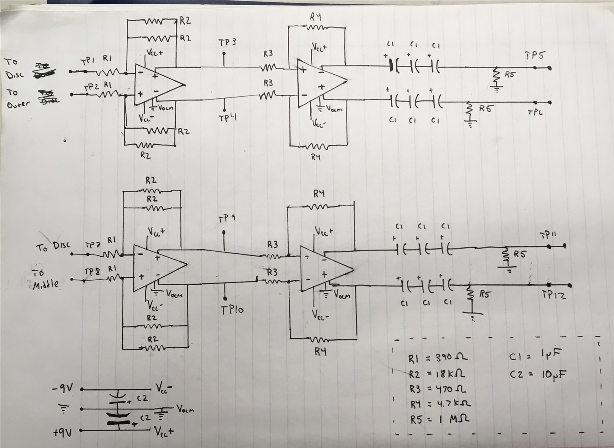
    Schematic is drawn below, exactly how it is laid out on a prototype board. Input signals are biosignals, so on the order of uV. We are seeing this issue when the inputs are open, though, and not connected to any source.

    Thanks,

    Richie

  • Hi Richard,

    sometimes low frequency oscillation can be seen, if a circuit is powered from a battery and the internal resistance of battery is too high. Buffering the battery voltage with a big electrolytic capacitor can eliminate this problem. You can easily check this by replacing the batteries with a well regulated power supply. A LM7805/7905 pair could be used for a test.

    Is the 13Hz oscillation you observe really 13Hz? Or is it a much higher frequency which only looks like a low frequency oscillation due to an aliasing-effect? Digital sampling oscilloscopes can show such strange artefacts sometimes. You can easily check this by first setting a very small horizontal time and looking for high frequency contents first. Then, increase the horizontal time until the oscillation becomes visible. And don't directly touch the outputs of THS4131 with the scope probe. Insert a small resistance of about 50R.

    Why not avoiding the unwanted coupling of the "disc's" signal by using a buffer for each signal first? This would provide very low source impedances to the inputs of THS4131, which can considerably help to stabilize the circuit. You can do the subtractions later. What is the bandwidth of your signals?

    Kai

  • Hi Richard,

    Did this resolve your issue? I agree that a buffer is a good solution. Just make sure it has over 145MHz of bandwidth otherwise it will not be low impedance over the operating bandwidth of the THS4131.

    Best regards,

    Sean