This thread has been locked.

If you have a related question, please click the "Ask a related question" button in the top right corner. The newly created question will be automatically linked to this question.

TLC3704: Recommended common-mode voltage limits

Part Number: TLC3704
Other Parts Discussed in Thread: TLV3704, TLV3494, LF411

I'm looking for some technical rationale for the common-mode voltage limit of Vcc-1.5V.

I have a legacy design that breaks this rule, but has worked just fine. (Vcc =3.3V, Vcm = 2.5V) I recently came across this limitation in the datasheet.

I am wondering why the limitation exists (from a part design perspective) and what failure modes (if any) are expected if this is exceeded.

This limitation is not noted as an absolute max in the datasheet. Is this stressing the part in some way?

  • Hello Chris,

    The input differential pair needs "headroom" for the upper current sources to do their job.

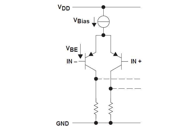
    Below is a very simplified diagram:

    The "Vbias" circuit requires about 0.8V to 1V across it to properly function. This creates the common mode limitation.

    If you pull the bases (gates) above the limit, it pinches off the transistors (MOSFETS), and it "kills" the input stage tail current.

    So in the case of the TLV3704, on a 3.3V supply, the valid input range is 0V to 2.3V.

    The limit is not a "cliff", as it does not suddenly stop working. There is a "grey zone" above 2.3V where the device "seems" to function, however specifications like offset and speed are degrading as you encroach into the zone and the input gets pinched off. At around 3V input, it may finally fail. This limit also changes over temperature - so if it is in the "grey zone", it may work at room temp, but may fail at higher (or lower) temperatures.

    The Absolute Maximum Input voltage is listed as "Input Voltage range" on page 2 of the datasheet. As long as keep the inputs within the Absolute Maximum specs ( -0.3 to VDD), there should not be any "damage", but it may not function correctly (incorrect output state).

    The TI precision labs segment on input limitations covers this issue:

     https://training.ti.com/ti-precision-labs-op-amps-input-and-output-limitations-1?cu=14685

    SO, obviously, the recommendation is to keep the input voltage within the specifications.

    You can either try to attenuate the input signals so they fall within the valid input range, or replace it with a Rail-to-Rail input device, such as the TLV3494 (slower).

  • Thanks Paul. That certainly clears a bit of it up. I have two follow-on questions regarding this.

    I assume the exact limits of this 'grey zone' will vary from part to part. Would testing each part over temperature be a valid method of screening? I'd expect the 'grey area' to change over temperature, but will it change over the life of the part?

    Would you be able to detail how you conduct your common-voltage range test? I see a couple test circuits in the datasheet but none specifically for common mode.

    Thanks

  • Hi Chris,

    The "Grey Zone" thresholds are dependent on the threshold voltages of the devices in that particular lot. Untrimmed/Untested parameters can vary up to 30% lot to lot over time - so you would need to put a large guard band in place.

    It will change over temperature and, obviously, the supply voltage. Drift over time is not expected. Pinching off the input stage is not really "stressing" it - so I would not expect it to drift over time.

    Still, it is not a good idea to operate outside the published specs (we have to say this...).

    We test using split supplies on the DUT, which allows changing the +V and -V to change the common mode point.

    You can use the test circuit in Fig. 6, but with the GND pin on the DUT(and R7) tied to a negative supply. The buffers and oscillator are also on fixed spit supplies.

    So assuming a 5V supply, you would apply +2.5 and -2.5V for a VCM of VS/2. The DUT common mode voltage would be in reference to the DUT "GND" pin (+2.5V) and system GND.

    So if you want to test at a VCM=+1V, then set the supplies to -1V and +4V.

    To test in the "Gray" zone at VCM=+4V, then set the supplies to -4V, +1V

    I would use LF411 type amps for the buffers and run them at ±15V. Their supplies need to be wider than the DUT supplies.

  • Chris
    We have not received a new post in a while so I am going to close this thread. If you have additional questions, feel free to respond to this thread again or open a new thread.
    thanks
    Chuck