This thread has been locked.

If you have a related question, please click the "Ask a related question" button in the top right corner. The newly created question will be automatically linked to this question.

TINA/Spice/OPA855: OPA855 Transimpedance Amplifier self-oscillation

Part Number: OPA855
Other Parts Discussed in Thread: TINA-TI,

Tool/software: TINA-TI or Spice Models

HI:

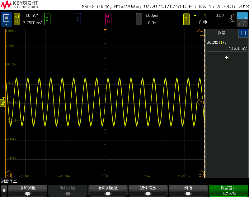
OPA855 Transimpedance Amplifier‘s Output self excited oscillation without input current.

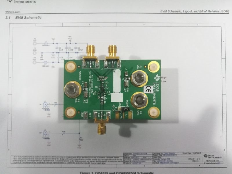
On the TI's OPA855DSG Evaluation Module.

There is no problem in simulation.so why?

THS!


 opa855.TSC

  • Hi Yu,

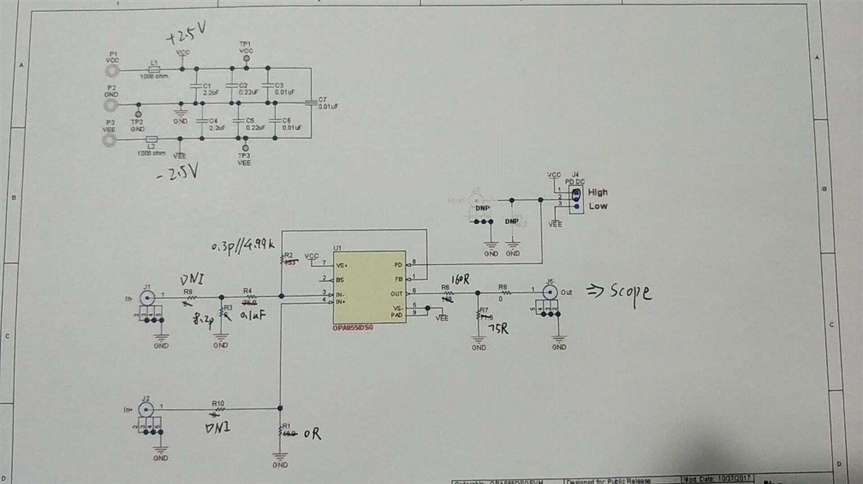
    how do you apply C3 to the circuit? When you set R4=0 you must not connect a cable to the -input. The cable capacitance would erode the phase margin and cause instability.

    How do you connect the scope probe to the OPA855? Directly at the output of OPA855? You should use a voltage divider at output of OPA855 to provide a load resistance of 200R, as shown in figure 43 of datasheet. The EVM has the same voltage divider.

    Kai
  • Hey Yu,

    It is difficult for me to see the components on the circuit board, could you take a higher resolution picture? Also, if the current is coming from the SMA connector without impedance matching, there is likely more parasitic capacitance than 8.5p on that node. A possible solution is to make R4= 500 or so (raise to minimize noise gain, lower to increase current), and instead apply a voltage signal, which will inject a current Vsig/R4.

    Best regards,

    Sean
  • Circuit details:
  • Hi Sean,
    Self oscillating without any input of current. R9 is not solder。
    Very Thanks.
  • HI Sean,

    I have retested and find that:

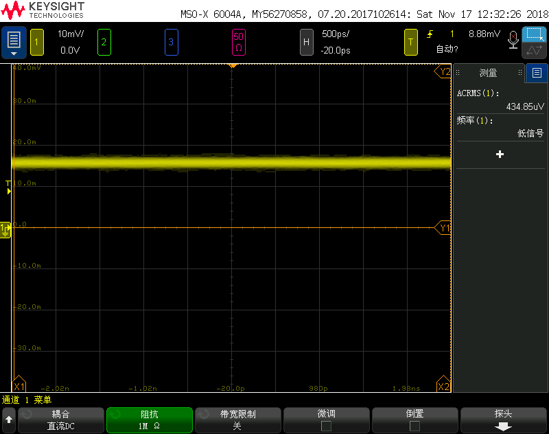
     If the input of scope is 1M terminal will not oscillate.


     If the input of scope is 50R terminal will oscillate.

  • Hi Yu,

    the OPA855 is an ultrafast decompensated OPAmp. Such an OPAmp can be very difficult to handle, especially when you remove R4 of EVM and directly manipulate the -input of OPAmp. R4 would isolate the impact of complex impedances from the outer world on the -input of OPAmp a bit. But when you remove R4 and do wirings directly at the -input of OPAmp, you must be very very careful. Even the least stray inductance and stray capacitance can ruin the performance. Every millimeter counts.

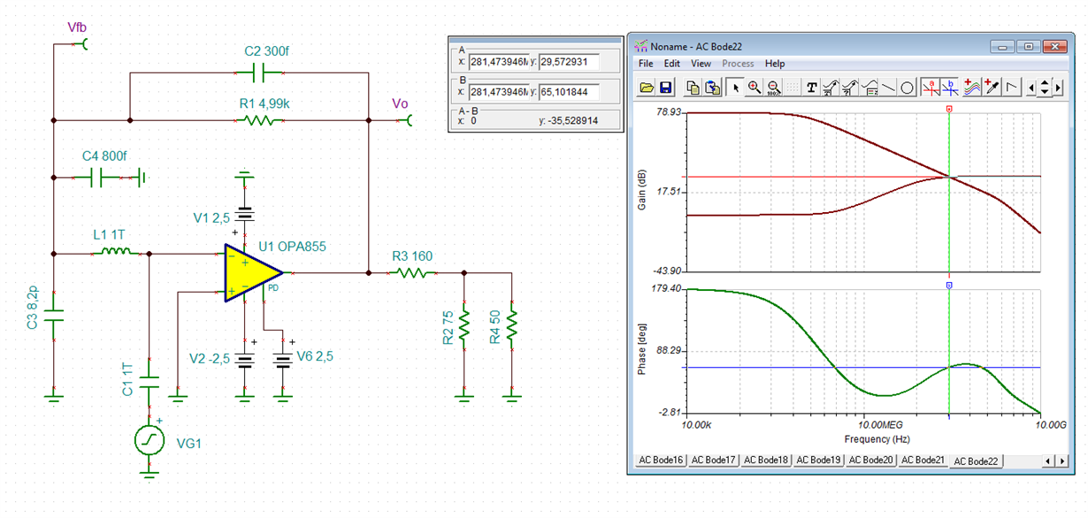
    The following phase stability analysis shows the performance assuming ideal components and an ideal wiring at the -input:

    So, the phase margin is 65° and everything is fine.

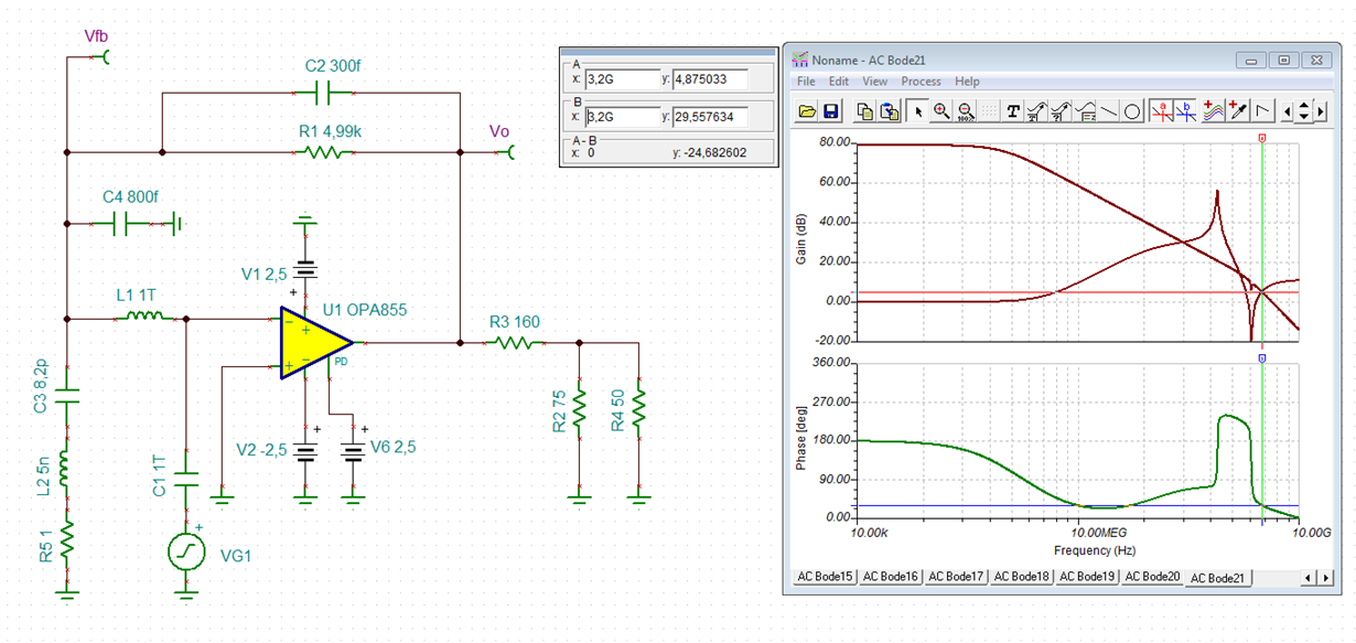
    But when you do not connect the 8.2pF capacitor directly to the -input, but have it mounted in some distance (R4=100nF !), then the copper traces on the board and the package length of "R4" will introduce about 1nH/mm stray inductance each and the following can happen:

    A total inductance of 5nH and a total ESR of 1R for the 100nF cap ("R4") and 8.2pF cap is assumed here. You can see that the phase margin breaks down below 30° at 3.2GHz, which is not enough for stable operation.

    There's another issue: With such a circuit the cable impedance matching should have an error of no more than 0.5%. That's why the EVM uses a 169R and a 71R5 resistor. Only with a perfect cable impedance matching the OPA855 output will not see the cable capacitance but only a pure resistive load.

    yu.TSC

    Kai