This thread has been locked.

If you have a related question, please click the "Ask a related question" button in the top right corner. The newly created question will be automatically linked to this question.

TLV1805-Q1: How the external protection parts work?

Part Number: TLV1805-Q1

Hello,

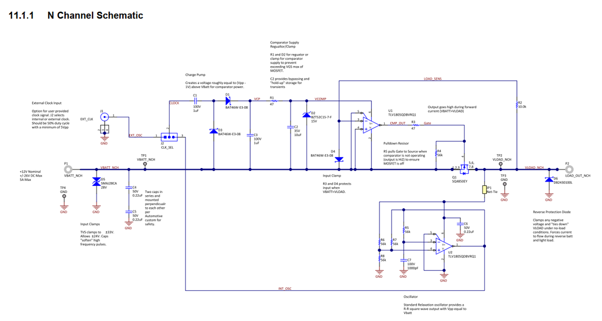
Would you please explain how the D4 Schottky between IN+ and IN- works? And in what situation? In the datasheet this is for an event like reverse supply, but I cannot understand what is the concern.

I would also like you to explain how the D6 Zener across the load works. I cannot understand how floating load can turn on the FET.

Thanks.

Oguri (TIJ automotive FAE)

  • Oguri-san
    Sorry that we are on a holiday break but we will address your question on Monday.
    Chuck
  • Hi Masatoshi,

    the polarity of D4 in figure 9 of datasheet is wrong! This has been corrected in the EVM:

    D6 makes sense during reverse battery and light load: If the N-MOSFET is eroneously turned-on, due to offset voltage of U1, e.g., D6 allows a high current to flow through the N-MOSFET for a brief period, which is high enough to make the drain more positive than the source. This is sensed by R2 and makes U1 turn-off the N-MOSFET. With a light load the drain source current might not be high enough to generate a sufficient drain source voltage across the Ron of N-MOSFET to make U1 turn-off the N-MOSFET. That's why D6 is needed. As soon as the N-MOSFET has turned-off, D6 allows furtherly a current to flow through R2 and D4 which makes U1 to keep on turning-off the N-MOSFET.

    Kai

  • Hi Kai,

    Thank you for the reply.
    But I still cannot understand about D6. For U1 to erroneously turns on due to offset voltage the voltage at IN+ and IN- must be almost the same. How can a high current flow through D6 in the situation?
    Moreover, how a current can flow through R2 and D4 in a light load condition? I guess it only can happen in a revers battery situation.

    Oguri
  • Hi Masatoshi,

    assume everything is fine and the input voltage is higher than the output voltage. Then the N-MOSFET is turned-on.

    Now assume that the input voltage is suddenly going negative (<0V!). At this moment D6 allows a high current to flow through the N-MOSFET for a brief period, which is high enough to make the drain more positive than the source. This is sensed by R2 and makes U1 turn-off the N-MOSFET. With a light load the drain source current might not be high enough to generate a sufficient drain source voltage across the Ron of N-MOSFET to make U1 turn-off the N-MOSFET. That's why D6 is needed. As soon as the N-MOSFET has turned-off, D6 allows furtherly a current to flow through R2 and D4 which makes U1 to keep on turning-off the N-MOSFET.

    Yes, I'm talking about reverse battery situation!

    Kai
  • Hello Oguri-San,

    Yes. D6 is for light-load reverse battery conditions. If lightly loaded (such as pre-start-up) , and depending on the offset of the comparator, the MOSFET could be held "ON" while the battery voltage swings negative. This would pull the load voltage negative below ground.

    This is important as the Reverse Current circuit is "floating" on VBATT, and has no ground reference, so it does not know it is going below ground.

    D6 would briefly conduct and force current to flow to trip the comparator. Otherwise, the load would need to act like the "diode", which may not be desirable..