This thread has been locked.

If you have a related question, please click the "Ask a related question" button in the top right corner. The newly created question will be automatically linked to this question.

INA225: Measuring small currents

Part Number: INA225

Hi,

I am trying to measure small currents with the INA225. (Imax 25mA) High-side 24V. Rshunt = 1Ohm. Gain 100. Vs = +5V.

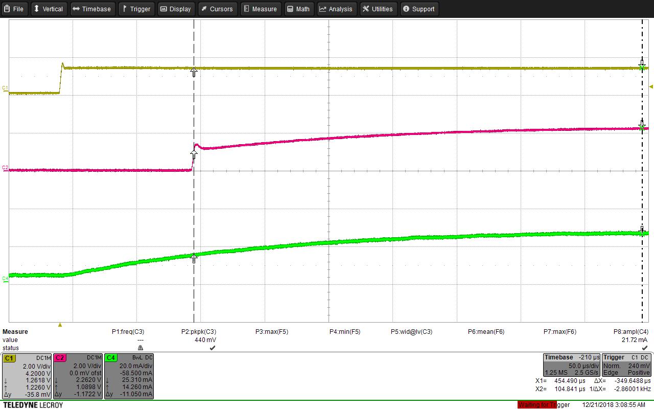
I have the following measurement C1 is a control step-input. C2 signal measured by INA225 (no load). C4 an external current probe. slowly rising current on C4 is OK (for the moment) there's a PMOSFET controlling the current, which is charging slowly.

What I don't like is INA225 starting to measure only at about 14mA (14mV). Is that behavior intended by TI? How can I know from the datasheet? What can I do better?

Second thing. For larger/faster steps, there is a delay of around 22us from input to output, that I cannot find a reason for.

Thanks for any help/correction/advise!

Simon

  • Sorry, it seems my pictures are not accepted...

  • before was measurement nr 2

    here comes nr 1

  • Hello Simon,

    Thanks for considering to use Texas Instruments in your design. Could you measure the +5Vstab line at the INA225 Vs pin when you apply the step response? If for any reason this Vs droops or is not at the expected value, this could possibly explain the delay. Another thing to check is your GS0 and GS1 pins when applying the step. If these change at all during the vstep, this could also produce a delay. Lastly, if these pin voltages look stable then you may want to see if putting a bias on the Ref pin (0.5V) helps. From a regulator or a buffered output would be ideal, but we think even from a voltage divider will be sufficient for this test.
  • Hello Patrick,

    Thanks for your advice. I just came back form holidays. Vs (+5V), GS0 and GS1 (0V and 3.3V) look fine. Additionally I tried reducing the gain. Didn't help, same curves at different levels.

    Your idea with Vref refers to chapter "8.2.2.2 Detailed Design Procedure" on page 22 of the datasheet, right? I'll check that, although my problem is with higher output levels than 10mV...

    This will take some more time, as I need to find a safe way to lift pin Nr. 7 from GND plane.

    Best regards

    Simon

  • Hello Simon,

    How has your design coming along?

    After looking this over I want to note a couple things. You will most likely get better speed and performance whenever your provide a reference voltage as Patrick suggested earlier. Biasing the output voltage with a voltage at the reference pin will position the output into its linear range and bring it out of saturation. Currently, the INA225 output is saturated at GND and thus there will always be a delay (overload recovery time) when VOUT has to drive out of saturation and into linear range.

    Another factor in all of this is the speed of your step input current. If your step input is very fast (NR2), then the INA225 will drive harder out of saturation. This results in a overload recovery time of 25us and rise time of ~10us. This is usually how overload recovery times are characterized for amplifiers. If the step input is slow (NR1), then the INA225 will not drive as hard and thus the delay time will increase. For NR1, overload recovery time is ~100us and the output tracks the slow input (C4).

    As I mentioned earlier, you can avoid the overload recovery delay times by positioning the output into the linear range, which for most parts will be >100mV. If you want shorter delay times, you could choose a current sense amplifier with high bandwidth.

    Hope this helps.

    Peter Iliya
    Current Sensing Applications