This thread has been locked.

If you have a related question, please click the "Ask a related question" button in the top right corner. The newly created question will be automatically linked to this question.

LM2917-N: Is LM2917 subject to latch-up or 'weird failures'?

Part Number: LM2917-N
Other Parts Discussed in Thread: LM239, , LM2907-N

Weird issue w/LM2917, and I'm stumped.

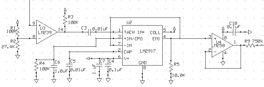
Used data sheet application circuit because it fit exactly what I was looking for.
Input of 2917 buffered with LM239 comparator, output is into LM285 opamp, with 10K to ground.
Good assembly/solder practices, anti-ESD measure in place.
Vcc is 15V
Works exactly as expected in breadboard, and on 6 of 16 assemblies.

The other 10? No output.
Replace LM2917's? Maybe 1 will work, replace  again... Maybe another 1 will work.
Take LM2917 from an assembly that works and swap around to the non-working boards, and they work fine.
If I keep replacing LM2917's, I eventually get 100% operational assemblies.
But that's a lot of LM2917's!

*It pretty much HAS to be something dumb*, but I've scoured the data sheets, and every application  anything that I can find.
I played with values, added additional decoupling to the circuit, and so on but didn't seem to make any difference.

Any thoughts or suggestions appreciated - I've never run into quite this issue before!

-K-

  • Hi William,

    have you read section 9.4.1 and 9.4.2 of datasheet of LM2917-N?

    Kai

  • I have, but hey it's a good idea to look again - so I rechecked - 8 pin package, pin 8 is ground and is internally tied to the comparator (-).
    (1) The circuit boards have been 100% trace checked. Pin 8 is directly to the ground plane.
    (2) Pin 3 has a 100K & 1uF ceramic cap
    (3) Signal is cap-coupled in, I can see the pulses crossing zero on the oscilloscope.

    This is low frequency stuff - like 100-200 Hz.

    It's not a matter of "the circuit won't function", it's a matter of either "the device is apparently destroyed at power up" - OR it works perfectly - including 48 hour burn-in looking for 'infant mortality' issues.

    Which is why I was asking about latchup or such.
    I see standard ESD warnings and such, and my assembly/work area has good anti-static setup.

    It's very puzzling.

    -K-
  • Hi William,

    have you noticed that the LM2917 (in opposite to the LM2907) has an internal zener diode at pin 6, with a threshold voltage of 7.56V?

    Can you show a schematic of your circuit?

    Kai

  • Sorry for the delay responding - holidays + death in the family have put me well behind in a lot of things unfortunately.

    Not sure what the relevance of the zener voltage is for this - can you explain what you're thinking?
    The circuit works - 100% reliability - except for a statistically aberrant number of 2917 failures at 1st power up.

    Vcc is 15VDC
    U3-9 is from a pulse source
    LM2917 circuit and values are directly taken from the app note - ~67Hz/V output is pretty much perfect for an output scaling.


    Any help is greatly appreciated.

    -K-

  • Hi William,

    in opposite to the LM2907-N, the LM2917-N has an internal 7.5V zener diode connected from pin 6 (V+) to pin 8 (GND). Have a look at section 9.2 of datasheet. And when you connect a +15V supply voltage to V+ you will barbecue this internal zener diode, unless the zener diode current is limited to under 25mA! You will need a current limiting resistor in series to pin 6, as shown in figure 19 of datasheet.

    Kai
  • I agree that a resistor is required if I were using the internal Zener regulation to cope with Vcc variations.

    However the data sheet shows in figures 15, 18, 23, 24, 25, 26, 28, 29, 30, 34 & 36 (all 8 pin LM2917) applications with no current limiting on pin 6 required. My Vcc is already well controlled enough for the application without using the Zener.

    Original breadboarded design phase I used 24VDC without issue, and I have multiple units that work perfectly fine with 15VDC applied for 48 hour burn-in, plus at this point at least several hundred operating hours.
    Any failures in the field would generate immediate - nearly instantaneous - customer feedback.

    However, I will definitely monkey around with some current limiting resistance values because at this point hey, why not? <LOL>
    And if that turns out to be the culprit, the data sheet will then win the very uncoveted "worst data sheet ever" award...

    BR,

    -K-
  • Hi Wiliam,

    maybe all the zeners were barbecued? And many of them without making the rest circuitry of LM2917 to fail??

    I agree, the datasheet of LM2917 is really annyoing!! :-)

    Kai

  • Gentlemen,

    The on-chip Zener diode was common in low power automotive/consumer devices in the 70's. All that was needed to create a local regulated supply was an external dropping resistor to the supply (and saves a Zener on the BOM). 8V was a common rail voltage for automotive circuits.

    With the advent of cheap and effective (and reverse voltage protecting) 3-terminal LDO's, these on-chip Zener regulators were no longer needed and fell out of favor.

    There are 4 input and regulator options in the LM2907/LM2917 family - so the 8-pin schematics generally depict the LM2907-8 as the "core" device.

    The LM2917 (w/Zener) was designed to be used with a 470 ohm dropping resistor on the supply line when supplied from 12V. The regulator also helped linearize the response over temp. You will note that several of the example circuits that depict LM2917 show a 470 ohm resistor in series with the supply (figs 19 - 22).

    If you are applying 15V directly to the V+ pin on the LM2917, then most likely you blew ("barbecued") the Zener regulator circuit on first power-up (it's actually an active shunt regulator - if you look at the section 9.2 schematic).

    If you take a new board and power it up, you will most likely see a large supply current for some time, then the current either falls to 'normal' as the zener circuit blows-out "cleanly", or the circuit fails if the Zener circuit blow-out damages the die.

    If this is the case, then the devices in the field are technically damaged and their longevity may be in question..Sorry....
  • Well... That's certainly interesting & useful information.
    Thank you  for answering the question - it is much appreciated.

    One more question, if you please: Is this information on the *requirement* for external current limiting resistance available on a data sheet, app note or such, and I just missed it?

    Because it *directly* conflicts with 15V shown being attached to Vcc in the example circuit on the data sheet and similar voltages >12V in multiple application examples.
    Same data sheet, the current limiting resistance is suggested as a means of improving operation with variable supply voltages, and absolutely nothing is said about being needed to operate reliably.
    No warnings about  operating >12VDC, or near/at the stated Vcc max of 28V requiring current limiting either.
    <sigh>

    Now to figure out how to  add that resistance, given the circuit board layout. Looks like board spin time.
    Happy, happy joy joy!
    And the logistics of replacing the fully potted units in field that are - regardless of survival/operation to this point - not acceptably reliable.
    Yeah, that's going to be expensive as hell since it scraps the entire unit.

    The data sheet gets a 0/10
    Would not use again.

    Do sincerely appreciate the information though.

    -K-

  • Hi William,

    see section 10.2.1.2.2, for instance. To be honest, there's lot of information about the zener distributed over the datasheet, if you read the datasheet really carefully, in a word-by-word manner. But I miss the clear statement somewhere, that the LM2907 DOES NOT contain the zener and that the LM2917 DOES contain the zener. And what this actually means for the developer.

    The main mistake can be found in most of the figures. Figures 15, 18, 23, 24, 25, etc. should explicitely mention that here the LM2907 is meant. And figures 19, 20, 21, 22 and 32 should explicitely state that here the LM2917 is meant.

    By the way, there is a very good appnote, which can be found on the LM2917 product page:

    www.ti.com/.../technicaldocuments

    In this appnote you will find many of the information you are missing when only reading the datasheet. Both documents must be read for a full understanding of LM2917!

    Despite all the hassle, the LM2917 is an absolutely fantastic chip!!

    Kai

  • Hello William,

    There are four variations of the family.

    The 8-pin versions have the negative input grounded internally. The LM2917 adds the Zener regulation across the supply.

    LM2907-14: Diff Input
    LM2907-8: GND referenced input
    LM2917-14: Diff Input, Zener Reg
    LM2917-8: GND referenced Input, Zener Reg

    Section 10.2.1.2.2 (page 15) describes the zener regulation for the LM2917 option. This has always been in the datasheet (as far back as my 1977 databook). The graphs show "470 ohm" next to the LM2917 curves. Technically, the Abs Max shows a maximum current, not voltage, for the zener option.

    I do agree that the example schematics are lacking exact device identification, as they are a mix of the '07 and '17 versions. But each one with the zener has the resistor.

    You do not need to do a board spin to add the resistance, just replace the existing LM2917-8 with a LM2907-8 (no zener). Essentially, you changed the LM2917 into a LM2907 by blowing out the zener circuit...so the performance should be the same.
  • LOL
    Yup.
    You are correct .

    Ya know, I read that app note multiple times, and somehow missed that. Completely.

    And now re-reading it? It sticks out like a sore thumb.
    And I'm feeling a bit "How'd you miss that, dude?" kind of derpy.

    Data sheet still stinks though.