This thread has been locked.

If you have a related question, please click the "Ask a related question" button in the top right corner. The newly created question will be automatically linked to this question.

THS3061: About the voltage reference for THS3061

Part Number: THS3061
Other Parts Discussed in Thread: OPA172, THS3062

Dear TI expert,

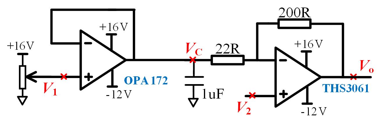
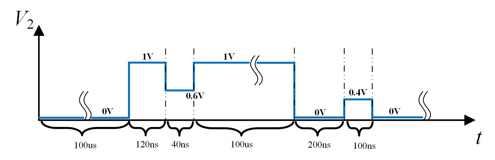
    Below is my schematic. I want to use THS3061 to generate output voltage Vo=10*V2-5, where V2 is between 0V and 1V. At present I use THS3061 as voltage-follower to make Vc follow V1 as 0.55V, and V1 is obtained by sliding rheostat as shown below. In my further design, to generate different Vo function, I may need to adjust Vc, whose value, however, will always be no more than 3V. 

    Besides the method I've adopted, I just wonder if there are better ways to obtain a more stable reference voltage, Vc ?

Regards 

Yatao

  • Hi Yatao,

    what do you exactly mean by "more stable"? Less sensitivity to wiper changes of trim pot? Or less noise? Or less dc voltage drift?

    Why do you use a 300MHz CFB OPAmp to generate a DC voltage?

    Kai

  • Hi Kai,

    I say "more stable" to mean that the dc voltage has less noise ,lower fluctuation and is more accurate.

    In my current design, I actually have used TI's OPA172 to generate the +0.55V to perform Vo=10*V2-5, where V2 is within 0 and 1V, hence, Vo between -5V and +5V. However, I find that when V2 is 0V, no matter how I adjust V1, VC is always below 0.26V. And when V2 is 1V, then VC is always above 0.75V. Hence I doubt OPA172's output ability, I choose to use a high performance OP: THS3062.

    Are there any better alternatives to generate a stable DC voltage?


    BTW, happy new year!

    Regards

    Yatao

  • Hello Yatao,

    What is the frequency range of V2? In terms of the OPA172, the bandwidth of the amplifier for the second stage may be the cause of not being able to generate the output range of -5V to 5V. With a gain of 10V/V, the output should stay within that range up to a frequency of around 330KHz.

    If the first stage will only be used to generate a DC signal, you do not need a high bandwidth device such as the THS3062 and can focus on choosing an amplifier with lower noise and drift specs that meet the requirements of your application.

    Best,
    Hasan Babiker

  • Hi Hasan,

    Actually, my current design is as below.

    V2's frequency is very low, in the range of several kHz, amplitude within 0 and 1V. To make THS3061 output within -5V and +5V, OPA172 should be preset to generate +0.55V. However, when V2 is set to 0V, I find Vc is always below 0.26V. When V2 is 1V, I find Vc is always within +0.75V and +1.25V. This seems to be related to OPA172's low output current capability(no more than 10mA). I change THS3061's resistor to 300R and 2.7k(different from TI's suggestion and maybe sacrifice 3061's performance), and then Vc can now reach +0.55V.

    Above all, I think OPA172's output capability too low to generate +0.55V with 22R and 200R. I have THS3061 at hand, hence I choose to THS3062 to generate +0.55V so that 22R and 200R can be used to preserve 2nd stage's 3061's high performance.

    Regards

    Yatao

  • Hello Yatao,

    The 10mA you are referring to is actually the absolute maximum current that can be applied at the inputs without damaging the device. The OPA172 has a short-circuit current capability of 75mA under typical conditions. The cause of these issues is likely due to the instability of the device with the introduction of a capacitive load (1uF). Is this capacitor needed for the application? If so, please reference section 9.2.1 of the OPA172 datasheet to find the right isolation resistor value to introduce to the first stage in order for it to be stable. I would also recommend simulating the device to ensure its stability using the techniques found here: training.ti.com/ti-precision-labs-op-amps-stability-3

    Best,
    Hasan Babiker
  • Hi Hasan,
    Thx for your reply.
    When THS3061 uses 300R and 2.7k to generate 10 times, I've used oscilloscope to observe Vc and find there seems no stability issues.
    Then why THS3061 uses 22R and 200R, when V2=0V, Vc can't be adjusted to above 0.25V; when V2=1V, Vc is always within +0.75V and +1.25V?
    If you guys don't know why,then maybe I'll need to use THS3061 to replace OPA172.

    Regards
    Yatao
  • Hi Yatao,

    it's not wise to bias a fast OPAmp (THS3061) with a slow OPAmp (OPA172). And it's not wise to load the output of OPA172 with an extremely low ohmic 22R resistance either. The OPA172 is optimized for loads >600R.

    What is the bandwidth of V2? Is the fast THS3061 (second OPAmp) needed at all?

    And please remove the 1µF cap from the output of the biasing OPAmp. That's bad design practise. :-) High capacitive load at the output of an OPAmp erodes the phase margin and destabilizes the OPAmp.

    Kai

  • Hi Kai,

    Actually V2 is a periodic waveform within 0V and 1V, and one period of V2 is given below, with amplitude and duration marked. It can be seen that V2's frequency is about 5kHz and period is 100us+12-ns+40ns+100us+200ns+100ns=200.46us.

    When V2 steps from, e.g, 1V to 0.6V, the design requires Vo should change as fast as possilble. That's why I want to use to THS3061 to generate 10*V2-5.

    So, do u think using ths3061 to generate the +0.55V for 2nd stage's THS3061 is a good idea?

    Regards

    yatao

  • Hi Yatao,

    ok, the use of a fast OPAmp makes sense.

    If I had to use the THS3061, I would do it this way:

    yatao10.TSC

    Kai

  • Hi Kai,
    You're very nice & brilliant!

    regards
    Yatao