This thread has been locked.

If you have a related question, please click the "Ask a related question" button in the top right corner. The newly created question will be automatically linked to this question.

TL082: Need to make a DC integrator to integrate a slow varying DC voltage over time

Part Number: TL082
Other Parts Discussed in Thread: TLV9002, LMV358, LM358

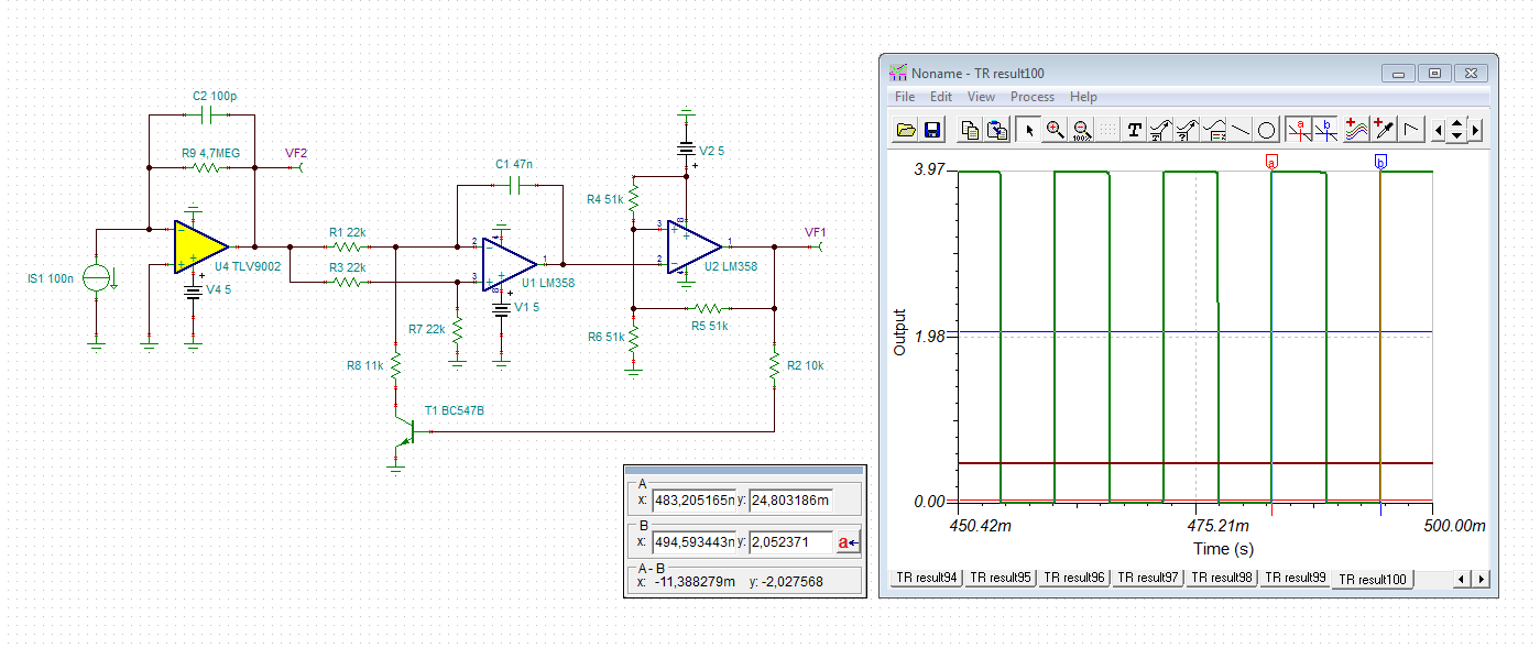
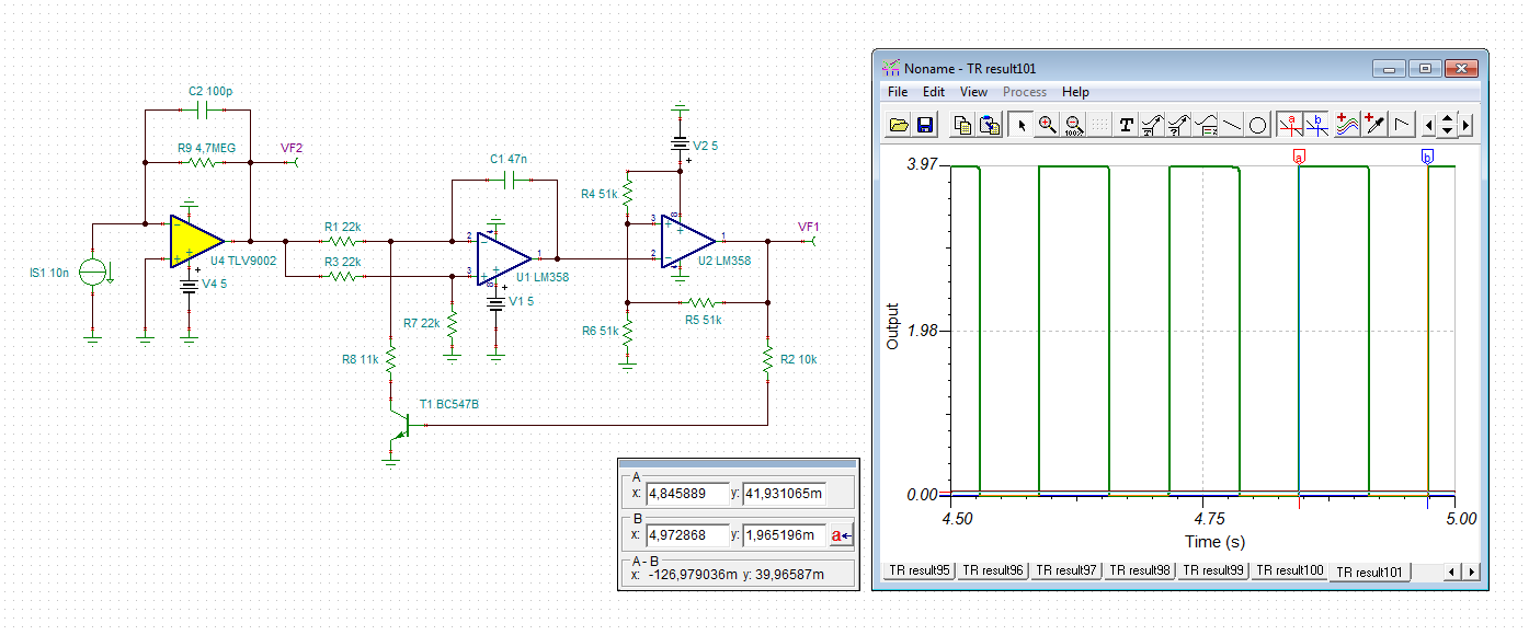
This is for sensing sunlight for a product in an agriculture environment. I have the transimpedance circuit already for converting the output of a photo diode to a voltage. The photo diode is looking at the sun from a greenhouse. I want to integrate that essentially DC signal over time. For the max voltage into the integrator (say 5 v) if that max voltage is present all the time I want the integrator to reach its max voltage after 5 minutes. I will short the integrator capacitor through a resistor after the integrator reaches its max output voltage to return it to zero. I am using 4.7 meg as the input resistor (R1) and also as the feedback resistor (Rf) and between 94 and 100 uf for the feedback capacitor (Cf). I believe this should give about 5 minutes of time (tau=0.69CfR1). I would use a TL082 (cheap; low offset V; etc) if it was single supply. I guess I could use EAGLE CAD to supply a circuit if needed. Looking for the right circuit and device (op amp) for this.

  • Alvin,

    Do you have supply voltage(s) chosen? Is it 5V? TL082 won't work well with that.
    5V and 4.7M is 1.06uA ; t = CV/I; t = 100uF * 5V / 1.06uA = 472s = 7.9 minutes
  • Alvin,

    For 5V, I recommend TLV9002
  • Alvin,

    For 5V, I suggest TLV9002
  • What was supplied was an AC integrator not a DC one.
  • Alvin,

    Can you provide an example of an integrator that only works with DC?
  • Texas Instruments app note in the early 70's has a jfet with r1 connected to first gate c1 connected to first gate and first drain. first source connected to ground. first drain connected to second source second gate connected to r r in series dropping the bias to one half VCC second fet used as a current source. It is amazing no one at TI knew how to solve this.
  • Texas Instruments app note in the early 70's has a jfet with r1 connected to first gate c1 connected to first gate and first drain. first source connected to ground. first drain connected to second source second gate connected to r3 r4 in series dropping the bias to one half VCC second fet used as a current source. It is amazing no one at TI knew how to solve this. Probably because you were not alive in the 1970 when discretes were used to solve problems not integrated circuits.
  • Hi Alvin,

    :-) you are a funny guy! Of course, we know how to do it, but we hoped that you would give some more details.

    It's not so simple to find a 100µF cap which isn't plagued by considerable leakage current and bias voltage caused capacitance drop.

    Apart from that, we are not here to do your design work, but only to help to get a chip work and fix issues in your design.

    By the way, many of the "good old" discrete circuits didn't work very well, you remember? And it's just the JFET which comes with huge manufacturing tolerances which can make problems here.

    Why not using a tiny microcontroller for all this?

    Kai
  • Alvin

    Like Kai said, we are waiting for more details especially VCC voltage so this design only needs to be completed one time.

    Max input is 5V (fastest output ramp) , what is minimum input (no output ramp)?

    In the 1970's I was repairing televisions with tubes.

    Anyway, I used your text to draw this. It seems incomplete.

  • second transistor drain is vcc. first transistor drain is output. top of resistor divider is vcc other side of r1 is dc voltage input. 

  • Hi Alvin,

    do you mean this integrator?

    But this is an AC coupled integrator, which can only be used for AC signals. This integrator is mentioned in this appnote:

    alvin.TSC

    Kai

  • Hi Alvin,

    I would do it with a digital integrator. A VCO could be driven by the TIA's output, like shown below:

    The output signal of TIA (brown curve) and of VCO (green curve) is shown for the photodiode currents 1µA, 100nA and 10nA. The periods of VCO output signals are 1.15ms, 11.4ms and 127ms. This corresponds to frequencies of 870Hz, 87.7Hz and 7.87Hz.

    The advantage of using a VCO is that you can scale the integration time very easily now. Connect a CD4040 binary counter to the VCO output and divide the frequency of VCO signal by a factor of 32, by using the output Q5 of CD4040. Connect this output to the input of a ICM7217. The ICM7217 is a counter with a 4 digit (7 segment LED) driver, which can count up from "0" to "9999". With a photodiode current of 1µA the ICM7217 needs 6.1 minutes to count up to "9999".

    When using the output Q8 of CD4040, on the other hand, the ICM7217 will need 49 minutes to count up to "9999". And when using the output Q11 of CD4040, the ICM7217 will need 6.5 hours to count up to "9999". In all these examples a photodiode current of 1µA is assumed.

    The CD4040 has Schmitt trigger inputs and is very easy to use. The ICM7217 is also easy to use. The whole circuit can be powered by +5V. Of course, any other VCO or frequency divider can be used here.

    Some words on the TIA and VCO: U4 is a TLV9002 because of its low input bias current, low input offset voltage, rail-to-rail capability at input and output and low cost. I have taken it because Ron has recommended it to you. For the VCO the LM358 is good enough. The simulation does not show any advantage, if the TLV9002 or the LMV358 is used instead of LM358. The VCO works down to a photodiode current of 2.5nA, at least in the simulation. Linearity of VCO suffers at very low photodiode currents. But I think one can live with it in this application.

    alvin2.TSC

    Kai

  • Actually I am going to do it digitally. My input is the output of a transconductance amplifier going to a ten bit AtoD. All I have to do is sample on a regular basis and add up the ten bit outputs. I already know what the upper value is that I want to integrate to so when the accumulator reaches that output then I know to trigger my operation. That time varies do to what the external environment does which is what I am measuring. Can't go into more than tat because it is my IP. I made the circuit I found and am not happy with their current source so I am just doing the analog version for my own education. I would do it under your spice but I do not know how to use it well enough yet. (TIAL-TI?) Anyway doing it digitally will let me more easily adjust the upper bound - or maybe more importantly let the user adjust it. Thanks for your help.