This thread has been locked.

If you have a related question, please click the "Ask a related question" button in the top right corner. The newly created question will be automatically linked to this question.

TLV3501: change the positive and negative alternating voltage into a square wave with positive amplitude.

Part Number: TLV3501
Other Parts Discussed in Thread: LM393-N

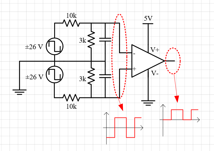
The input voltage is alternative voltage with positive and negative. For easy understanding,  I put two same square wave sources which only have +26 V and -26 V, and it means the input voltage of AMPLIFIER(divided by resistor)is +6V and -6V to the both input pins (to GND). It can change the alternative voltage source(with -6V and +6V) to a square wave(only with +5V and 0V). But the amplifier TLV3501 V- is connected to GND, so when input pin connected to -6V, it can be forced down to -0.3V of this pin. So is there a hidden danger in this circuit?

And if it is, any suggestion can you put forward?

  • Hello,

    No. +6V and -6V is much too high. The legal input range with a single 5V supply is +5.2 to -0.2V.

    The inputs are protected by ESD diodes to the supplies:

    The negative swing will be clamped by the input ESD protection diodes, at about -450mV. The positive swing will be clamped to V+ by a similar amount.

    This is not ideal - the input range is exceeding the valid range and you are stressing the ESD diodes.

    The simplest solution is to increase the divider ratio so the ±6V becomes less than ±200mV, and stays within the valid input range. Comparators do not need an absolute value - just relative levels.

    So if you change the 3k resistors to 75 ohms, then the input signals are reduced to an acceptable ±194mV.

    Otherwise, you will need to add external attenuation and clamping. It is also possible to level-shift the input using pull-up resistors - but that does get complicated.


  • First, thank you for your patiently answer!

    Actually, the input voltage sources I set above are not square wave but trapezoidal wave(From the auxiliary winding of transformer and the primary is +&- 400, turn ratio is 15:1:1, so the above source is +&- 26V). I mean the falling edge of the wave is not infinite, so I want to capture the ZERO-CROSS point and then use the level flip to my circuit. 

    So, adjusting the divider ratio may affect precision. 

    I will try to use your suggestion and see the result.

    Thanks!


  • Since there has been no further question for a while, I am closing this post. If you have further questions, feel free to reply and the post will be re-opened.
    Chuck
  • Hi,

    figure 31 of datasheet of LM393-N shows a very nice zero crossing detector. Would this help you?

    Kai