This thread has been locked.

If you have a related question, please click the "Ask a related question" button in the top right corner. The newly created question will be automatically linked to this question.

TINA/Spice/OPA549: SINE Wave current 5A for testing CT

Part Number: OPA549
Other Parts Discussed in Thread: TINA-TI, , OPA541

Tool/software: TINA-TI or Spice Models

Dear All,

I meet some problem, I made a board with a OPA549 for testing a CT.

The problem is my Voltage supply (+V & -V) sucked down. (i used a external power supply +35V/-35V)

And the ouput is zero.

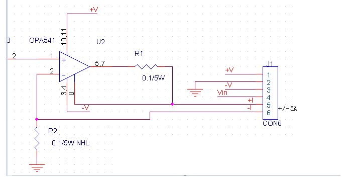
This is my circuit :

  • Hi Aymen,

    There really isn't enough information about your OPA541 application for us to determine what may be occurring in the circuit to cause the +V and -V supplies to be pulled down. If the OPA541 has been damaged that certainly can produce that kind of behavior. Do all OPA541 devices do this, and once they do does it always happen? Have you monitored the OPA541 +V and -V pins with a DSO when they pull down?

    Please provide information about the input source characteristics, the actual load and its characteristics, what the OPA541 is supposed to be providing to the load and any other circuit connections such as power supply bypass capacitors used for +V and -V. Are you sure your external power supply is capable of providing at least 5 Amperes of current?

    Do you have the tab of the OPA541 TO-220 package connected to -V in your circuit?

    Regards, Thomas
    Precision Amplifiers Applications Engineering
  • Hi Aymen,

    I just noticed your schematic shows OPA541, but the question is about OPA549. Which device are you using in your circuit? My preceding remarks and questions apply to either device.

    Regards, Thomas
    Precision Amplifiers Applications Engineering
  • Hi Thomas,

    Sorry For this mistake, I use the OPA541 and not the 549.

    For my problem i wired the component like the schematic, i used for my test this power supply : 

    https://fr.rs-online.com/web/p/alimentations-de-table/6654903/

    On my DSO I had a saturated signal of 100 mV (without current).

    The input signal provided by a low-frequency generator.

    And the load is a small resistance of 0.02ohm 2W.

    Regards Aymen,

  • Hi Aymen,

    I am pretty certain that the OPA541 as configured is drawing more current than the power supply can provide. With the 100 milliohm current limit resistor the OPA541 can supply up to 6.8 Amperes. This is occurring because you are driving the 20 milliohm load to ground with a voltage source configuration, and it doesn't take much over 100 mV of input voltage to exceed 5 Amperes of output current. The 20 milliohm resistor looks much like an output short to ground and the op amp is working to go into current limit protection mode. You can see a TINA Spice simulation below where as little as 100 mV input results in an output current greater than 5 Amperes. Since your adjustable power supply has a maximum current output of 4 Amperes the V+/V- outputs will collapse if any greater current load is presented i.e. the supply is going into current limit shutdown mode and voltages likely go zero.

    There are relatively simple current source circuits that will provide more predictable output current and you can avoid exceeding your power supply's maximum output current by keeping the output current within its limits. Google op amp current sources and you should find various circuits. A popular power current source circuit is the Improved Howland Current Pump and many customer designs use it.

    Regards, Thomas

    Precision Amplifiers Applications Engineering

  • Aymen

    We have not heard back from you so we will close this thread. Please reply if further discussion is needed.

    Regards
    Dennis