This thread has been locked.

If you have a related question, please click the "Ask a related question" button in the top right corner. The newly created question will be automatically linked to this question.

LMH6629: Noise figure curve in data sheet with unterminated structure

Part Number: LMH6629

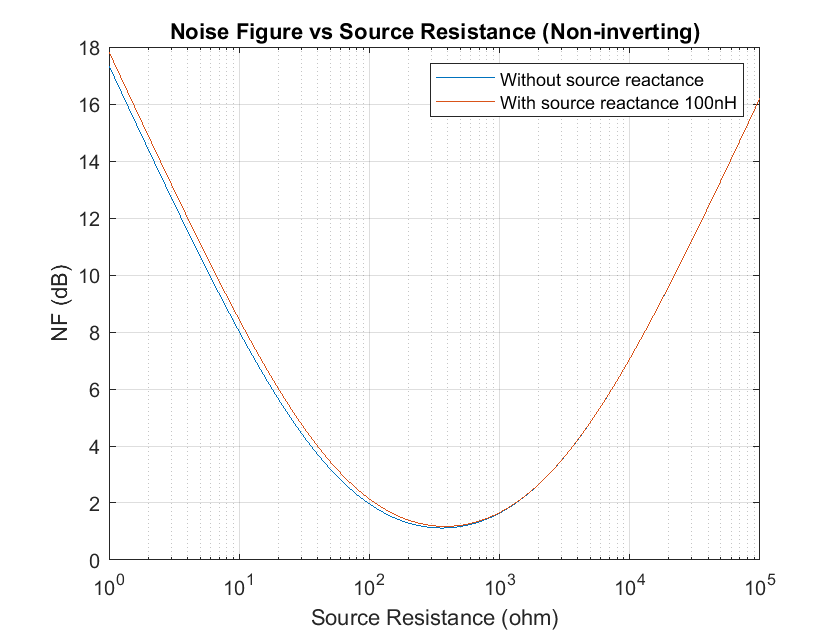
Recently I was testing noise figure of LMH6629 with noninverting structure (unterminated case). However, I am not able to acquire Fig. 58 data in the data sheet. The noise figure presents out not stable across frequency range from 20 Mhz to 200 Mhz when source impedance is 50 ohms (no terminated resistor). My question is, how do you acquire the noise figure curve in Fig. 58? Is that a simulated noise figure curve or measured noise figure curve? If it is a measured noise figure curve, then how do you measure unterminated case noise figure?

  • Hi,

    Do you have the device configured exactly as shown in figure 52 of the datasheet? Also, how long is your input cable to the device? If you are unterminated at high frequency you could potentially have reflection errors in the cable if it is long enough.

    Regards,
  • Hi Timmit,

    what is your setup?

    Usually no cable should be tied to the input during the measurement. Just have the necessary resistors from figure 52 close to the chip, use the recommended supply voltage filtering and shield the whole circuit. Connect the shield to signal ground. If you connect a cable to the output, don't forget to provide series termination. Use a 50R series termination resistor when using a 50R cable and measuring equipment with 50R input resistance.

    Kai
  • Jacob,

    I think I used same structure as described in Figure 58. For Rf=240 ohm and Rg = 27 ohm. However, there is a series 50 ohm resistor at output of the chip for matching to spectrum analyzer. The input cable is already taken into consideration which is 0.83 dB loss. I do understand that there must have reflection when operating at 200 Mhz. That is why I am asking that how do data sheet get those curves? Do they simulate or measure unterminated NF curve?
  • I am using Y-factor approach to calculate NF. The experiment diagram is attached. Typically, I used two 50 ohm resistors placed at room temperature and liquid nitrogen. Then, I can calculate Y value by measuring two noise floor level with spectrum analyzer HP4395A. With two known temperature and Y value, I am able to calculate noise figure of the DUT. There are cables between DUT and the resistors, but this can be remove by calculating loss of cable (RG58). The output of the DUT is connected directly to spectrum analyzer. With this setup, the overall NF across different frequencies, e.g. 30 mhz, 50mhz, 80 mhz, 200 mhz, presents unstable for unterminated case, but not for terminated case. I do realize that this could be due to impedance not matched at input of the DUT. Thus, my approach may not be correct. So I'd like to know that if the NF curve (unterminated case) in Figure 58 is a simulated NF curve or a real measurement? If it is a real measurement, then I'd like to know that the experiment setup? If it is a simulated curve, then I think it should correspond to my simulation shown in the attached file.

  • Hi Timmit,

    We use a noise source (I believe it's diode based) along with a spectrum analyzer to measure the noise figure for both the terminated and unterminated cases. I can get you the exact model number if you are interested.

    How long are the cables between your resistors and the DUT? I'm wondering if the unterminated connection could be causing reflection issues that might show up as an unstable measurement.

    Regards,