This thread has been locked.

If you have a related question, please click the "Ask a related question" button in the top right corner. The newly created question will be automatically linked to this question.

TIDM-BIDIR-400-12, current sensing amplifier,

Hello everyone. 

This question is coming from the thread below. 

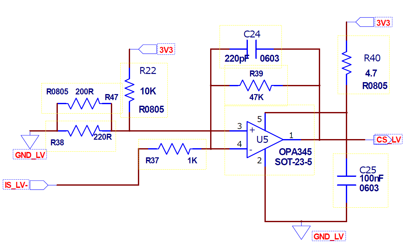
I'm dealing with the Current sensing part of the TIDM-BIDIR-400-12 reference design. 

As I explained the thread above, I have still the problem on ADC circuit on design. 

Let me explain one by one. 

In designed(my hardware) circuit, 0.0005ohm shunt resistor exists for the current sensing.  

1. In 10A output current condition, measured with DMM, almost 5mV is measured between two sides of the shunt resistor. 

2. But when I measured the IS_LV- to the ground, showed almost three times the value. (almost 13mV)

3. The offset voltage of the circuit can be measured correctly, and also can be shown correctly in ADC real-time value table in CCS debug mode. 

4. As a result, when I increase the output current by 1A, ADC value feels like I increase 3A. 

5. Furthermore, after the output current reaches 12A, ADC value shown in Real time value table in CCS debug mode went down even if I increase the current. 

At that moment, PIN 3 and PIN4 voltage starts to go far different value(41mV VS 21mV) 

6. I realize the OPA345, op-amp of this circuit is revised by OPA365 in the newer version. I changed the opamp but it didn't change any situation. 

As you recommended last thread, I checked the excel calculation file, and analyze the code with ccs, I think this is not a problem of software or code. 

What can you recommend for this situation? I'm dealing with this problem around 6 weeks, I'm still curious about this matter, and I want to know which part is the problem,

  • Hi Kyoungtak,

    I saw you created another thread which is exactly the same with this one. But this one has the link to the original thread which is good. I will go ahead to close that one and let's discuss under this thread. Thanks.

    Regards,
    Chen

  • 1. In 10A output current condition, measured with DMM, almost 5mV is measured between two sides of the shunt resistor. 

    2. But when I measured the IS_LV- to the ground, showed almost three times the value. (almost 13mV)

    Based on your description, it seems like it is not a problem in the code as you mentioned.

    The signal that goes into the ADC is not correct. It is either something wrong with your measurement or the hardware.

    However, base on the schematic shown below. The value you measured in step 1 and step 2 should be the same. Should the measurement point be the same? 

    Regards,

    Chen

  • Thank you for your reply. 

    I measured the voltage between two sides of the shunt resistor like this.(I'm intend to explain how I measured these components, the rest of the components are soldered) 

    And also I measured IS_LV- to GND like this. 

    former side of the R37 to GND. 

    In my result, ADC is measured exactly the three times of the real value as I measured the voltage between R37 to GND. 

  • Hi Kim,

    Did you have any progress?
    I think you need to figure the problem out one by one by first looking at the wired ADC value in step 1 and 2.
    The input to the ADC is the output of the op-amp. Can you list the measured value and ADC value seperately(I mean the exact number)? I am still confused about your problem.

    Regards,
    Chen
  • Thank you for your help. 

    This is the value I got from the experiment.  

    Output current, adcresult4, ILV-FB voltage, IS_LV voltage is measured in hardware. 

    Calculated IS_LV voltage is calculated by (ILV-FB voltage - 1647.4)/47 equation. 

    when it reached around 20A, the adcresult4 value is stuck in 3800. 

  • Hi Kyoungtak,

    The simulation you attached in another thread as below is the reference that you need to match. 

    The problem is why the IS_LV- is 12.862mv instead of 5mv in you circuit.Have you tried to replaced your op-amp?Or try to disconnect the op-amp circuit to check the sensing problem. This is the first issue that you need to check in your circuit. Thanks.

    After that, then please check the voltage CS_LV to whether that is correct or matching the simulation results.

    Based on your results, I think there is something wrong in your sensing circuit before reaching ADC. Thanks.

    Regards,

    Chen

  • Hi Kyoungtak,

    Do you have any updates? Does it solve the problem?

    Regards,
    Chen
  • Thank you for your help.
    I can't find any problems anymore,
    So I re-ordered the PCB and I'm waiting for that.
    Until it comes, I 'm using the current tranducer(LEM LV100-P) to give current information directly to the MCU.
    Thanks.
  • Hi Kim,

    Thanks for your updates, feel free to come back if you find any other problems. I will go ahead and close this thread since it might take some time for you to finish the new test and you can create a new one and link this thread if needed.

    Regards,
    Chen