This thread has been locked.

If you have a related question, please click the "Ask a related question" button in the top right corner. The newly created question will be automatically linked to this question.

TLV9064: GBW spread

Part Number: TLV9064
Other Parts Discussed in Thread: TINA-TI

Hi all,

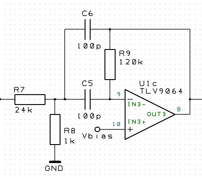
I'm using a TLV9064 quad op-amp in a cascaded active bandpass filter configuration. I fine-tuned my design using simulations and all is working fine now. But despite the 10MHz GBW of this op-amp the center frequency of my band-pass filter is still slightly dependent on variations in GBW. 

The datasheet only mentions a typical value for GBW. Is there any information available about the variation in GBW? Does it also change with temperature?

Thanks.

Paul

--

  • Hi Paul,

    bandpass filter are critical, especially if they are using high Q. They need much gain headroom and probably you have moved the center frequency of bandpass filter too close to the unity gain frequency of OPAmp and/or have chosen a too high Q / gain. With a proper design variations of GBW of OPAmp should not have any impact on the frequency response of bandpass filter.

    Can you show a schematic?

    Kai
  • Hi Kai,

    Thanks for the quick reply.

    My filter consists of four identical cascaded sections like below:

    The center frequency is supposed to be 137kHz which it is if GBW is 10MHz. When I change the GBW in the simulation to 12MHz the center frequency goes up to approx. 139kHz. My prototype also produces a peak at 139kHz which leads me to believe that the actual GBW of my op-amp is closer to 12MHz.

    Regards,

    Paul

    --

  • Hi Paul,

    Regarding the gain-bandwidth variation of the device, a general rule of thumb is that it can shift 30% across temperature, process, and variation. It is difficult to specify a maximum value because of how much this parameter depends on.

    -Paul
  • Hi Paul,

    your bandpass filter has a Q = 5.6. A rule of thumb says that the OPAmp needs an open loop gain of 20 x Q^2 = 630 = 56dB at 137kHz then. But the open loop gain plot in figure 6 of datasheet tells that the TLV9064 has only 38dB. So, the TLV9064 is too slow for your application. The result of your simulation is correct. I can verify this in TINA-TI, too, when I modify the DC open loop gain.

    Kai
  • Hi Paul,

    Thanks for the reply. 

    Is that + or - 30% or the total span?

    Paul

    --

  • Hi Kai,

    I could live with a small deviation in the center frequency of my filter, as long as its extremes can be controlled. I also have some slack in the requirements of the Q and could possibly reduce this a bit while still be able to use it for the intended purpose.
    A faster (more expensive) opamp is not really an option since we are pursuing a certain price point for our product.
    With minimum and maximum values for GBW I could make an estimation of the worst case effect on filter parameters and find the best trade-off between Q and center frequency that still meets my requirements.

    Regards,
    Paul
    --
  • Hi Paul,

    the ideal center frequency of your bandpass filter should be 148kHz and not 137kHz. This shift is already a consequence of the finite bandwidth of TLV9064. Another issue is that the cap values of your bandpass filter are rather small and that the input capacitance of TLV9064 can already play a role.

    I would give this circuit a try:

    It provides nearly the same gain and the same center frequency but a Q of only Q = 2.7.

    This is the performance of your original bandpass filter:

    paul1.TSC

    Kai

  • Hi Kai,

    I'm not sure if I can get away with a Q of 2.7. I need a certain selectivity for my filter for the succeeding circuit to work properly.
    I ran some simulations and a Q of 3.5 might just be sufficient. I also tried to increase Q by adding a small amount of positive feedback to the non-inverting input and that seems to mitigate the sensitivity to GBW. I'm not exactly sure why and where I'm paying the price.

    The reason for the 100pF caps is that this particular value in NP0 and 1% tolerance can be had relatively cheap. But parasitic input capacitance is a good point and I might have to revisit this.

    Paul
    --
  • Hi Paul,

    why not using a state variable filter (three-OPAmp bandpass filter)? The minimum open loop gain of OPAmps at the center frequency would only be 3 x Q. This is a drastical improvement over the one-OPAmp bandpass filter which needs a minimum open loop gain of 20 x Q^2.

    Kai
  • Paul,

    The spread is +/-30%. For a 10MHz device, you might expect to have some units that are closer to 7MHz and others that are closer to 13MHz. This is just a rule of thumb thought that captures variation over a wide range of parameters.

    Thanks,
    Paul
  • Hi Kai,

    I now have 4 identical sections giving me a total Q of about 15.

    Would that be achievable with a state variable filter with only 3 opamps?

    I' m not familiar with this topology but I'm open to sugestions.

    Regards,

    Paul

  • Hi Paul,

    Is it safe to assume that the 4 opamps in one package all have the same GBW or does the 30% also apply to the individual amps within the package?

    Paul
  • The op-amps in a single package will track much more closely together - temperature changes will basically effect them equally (assuming there is even heating across the die). Process variation will be less of a concern as well because the amps are in the same silicon substrate.

    I don't have a good number or guideline, but I would guess that the measured GBWs for each channel are within 5-10% of each other.

    -Paul
  • Hi Paul,

    such a state variable filter could look like that:

    paul2.TSC

    Unfortunately, the simulation of this circuit doesn't work very well. The gain is much higher than theory predicts. So, I don't want show any results of the simulation. Don't know why...

    The schematic might nevertheless be helpful?

    Kai

  • Hi Kai,

    I did some playing around with this topology and I managed to get it working in the simulation. The nice thing about it is that you can change Q without affecting the center frequency and vice versa. 

    And the GBW sensitivity of Fc is indeed much less then in my original filter topology, just like you mentioned.

    But what I also found is that instead of Fc being dependent on GBW, now Q varies with GBW. That leads to the gain of the filter at the center frequency being variable which is another problem.

    Another difference is that the roll-off on both sides of Fc is basically 1st order 20dB/decade where in my cascaded filter it is fourth order 80dB/decade. So in the vicinity of Fc the filter can be made quite steep by increasing Q but at the far ends of the frequency range the attenuation is limited.

    I'm not sure which way to proceed yet ,but this was a very educational exercise anyway.

    Thanks,

    Paul

    --

  • Hi Paul,

    your observations make absolutely sense to me.

    Don't beat me, but would an additional passive RLC-bandpass help?

    paul3.TSC

    R2 and C2 simulate the parasitics of B82144B choke.

    Kai

  • Hi Paul,

    was the tip with the passive RLC-bandpass helpful?

    Kai
  • Hi Kai,

    Sorry for not replying earlier.

    I had considered using a passive RLC filter earlier in the design process, but the need for a relatively large value inductor made this too expensive. I also experimented with smaller valued inductors but then the capacitors (which then become larger and need to be NP0 for accuracy) became too costly.

    I think I have found a solution now where I can tune the center frequency of the active filter in order to adjust for differences in GBW.

    So far that seems to work.

    Regards,

    Paul

    --