This thread has been locked.

If you have a related question, please click the "Ask a related question" button in the top right corner. The newly created question will be automatically linked to this question.

OPA320: Effect of signal source internal resistance on voltage follower - opa320

Part Number: OPA320
Other Parts Discussed in Thread: INA240, ADS131A02

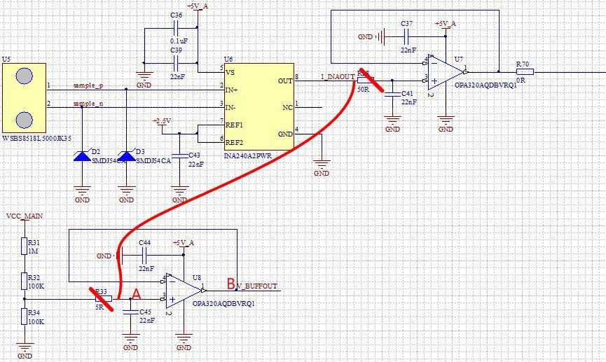
In my design, I used opa320 in two places, voltage detection and current detection.

Current detection

A and B are almost equal.
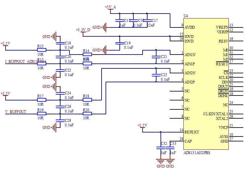
Voltage detection

The resistance is temporarily selected to 5% accuracy,VA=4.14049V,VB=4.17855V,ΔV=38.06mV

Then, I tried the following

A and B become almost equal.

What is the difference between the two inputs?

The input impedance,because the output impedance of the amplifier is very small.

So,my guess is that the input impedance of the source is the cause.

Then, I tried to lower the input impedance: R31=10K,R32=1K,R34=1K. The voltage is reduced by taking into account the power consumption of the resistance.VCC_MAIN=24V.

The results are as follows: VA=1.97123V,VB=1.97141V,ΔV=0.18mV.  It's improved a lot.

The input impedance of the voltage follower is infinite, will the 1M resistance affect it so much?

In addition, the magnification tends to be 1 but not greater than 1.The signal source internal resistance will share a part of the voltage, why is the output of the voltage follower larger than the input?

Thanks for your help !

  • Hi Liang,

    R28 must not removed, because this will make the INA240 become unstable in combination with the capacitive load of 22n! R33, on the other hand, can be omitted, provided R34 and C45 are close to the +input of U8.

    Are you sure that the input voltage at point "A" is never exceeding the common mode input voltage range of OPA320? Can you show scope plots of the input signal at point "A"?

    Take care, the OPA320 is very fast. You should not directly touch the output of OPA320 with the voltmeter or scope probe. Insert a small resistor of about 47...100R for the measurement. Read section 7.3.8 of datasheet of OPA320.

    Of course, in normal operation the output of OPA320 must be isolated from capacitive loads as well! What have you connected to the outputs of OPA320?

    Kai

  • Hi Kai,

    Thank you for your answer.

    The R28 was removed for fly-wire testing on the circuit board, yeah, there are risks associated with the capacitive load. But the effect of the two input impedance on the output is confirmed.

    I'm sure that the input voltage at point "A" is never exceeding the common mode input voltage range. Voltage detection is used in the battery. The maximum voltage of the battery is 54.6V, and the maximum voltage after one-twelfth of the voltage is 4.55V.

    The data are obtained by means of a high-precision voltmeter.

    After passing through the filter circuit, the output is transmitted to ADC (ADS131A02), and then the digital quantity is sent to DSP (28335). Even if the voltmeter may affect the circuit or the measurement, the data amount obtained by DSP is quite different from the theoretical value of 1/12 without the voltmeter.

    Liang

  • Hi Liang,

    these many 100nF caps at the output of OPA320 is an extreme capacitive load for a 20MHz OPAmp! This almost looks like a short circuit for fast changing signals:

    opa320_1.TSC

    I would make the 100nF filtering caps smaller.

    Kai

  • Hi Kai,

    I tried the simulation and I got it.I will change the capacitor and actually test it when I go to work tomorrow.

    In addition, can you explain the effect of the internal resistance of the signal source on this circuit?

    I changed the signal source internal resistance of the simulation circuit to 1M, and the result is as follows. Overshoot improved.

    Liang

  • Hi Kai,

    Can you explain why the spike is there?Shouldn't that be where the high level starts and the capacitor starts charging?

    In addition,does a spike with such a short duty cycle make a big difference to the average of the measurements?

    Thanks for your help!

    Liang.

  • Hi Liang,

    I think it has to do with the internal output current limiting circuitry, which has the purpose to limit the output short-circuit current. Of course, the short-circuit limiting would only invoke, if your input signal contains steep edges...

    Kai
  • Hi Kai,

    Another question? The effect of the internal resistance of the signal source.

    Liang
  • Hi Liang,

    I don't know why this plays a role. Maybe the OPAmp works better, if the input signal is farer away from the supply rail?

    But I think it could also have to do with the huge capacitive load at the output of OPA320. Reduce the capacitive load for a test and see what happens. Add a small resistor of about 47...100R to the output of OPA320 during the measurement. Do not directly touch the output of OPA320 with the voltmeter or scope probe!

    Kai

  • Liang

    We have not heard back from you so we will close this thread. Please reply if further discussion is needed.

    Thanks
    Dennis