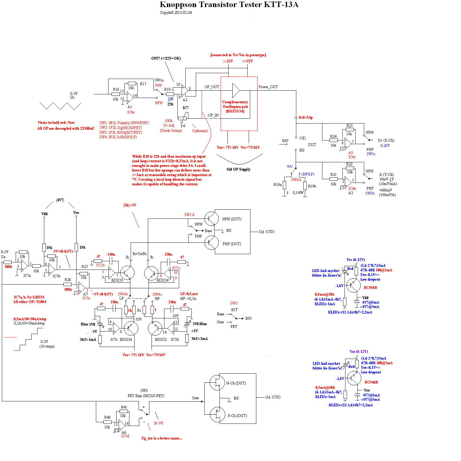
This thread has been locked.
If you have a related question, please click the "Ask a related question" button in the top right corner. The newly created question will be automatically linked to this question.
Replies: 38
Views: 2697
Part Number: TL084
Hi!
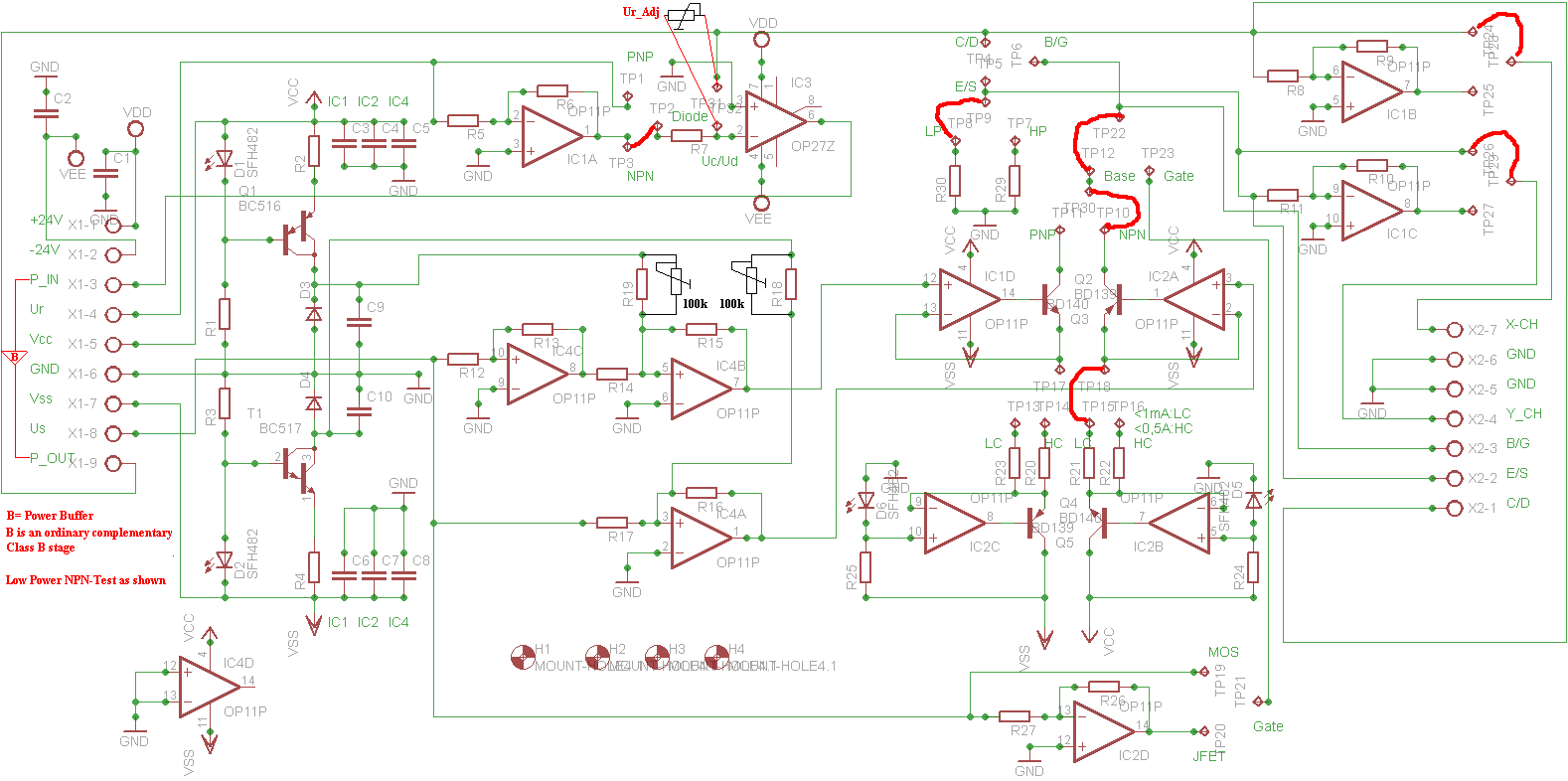
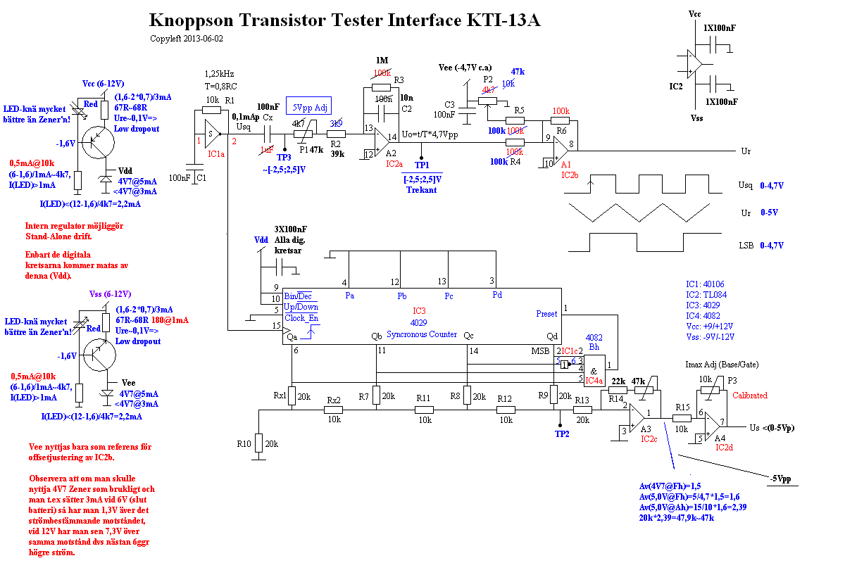
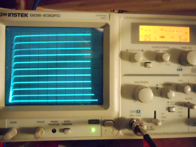
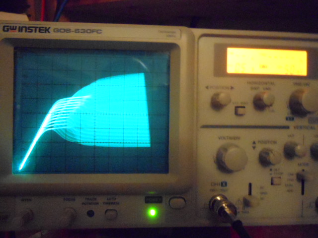
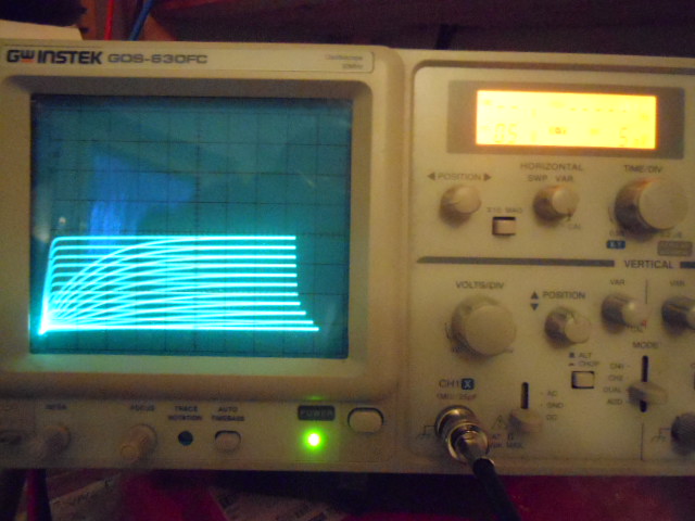
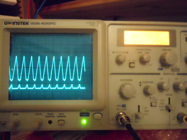
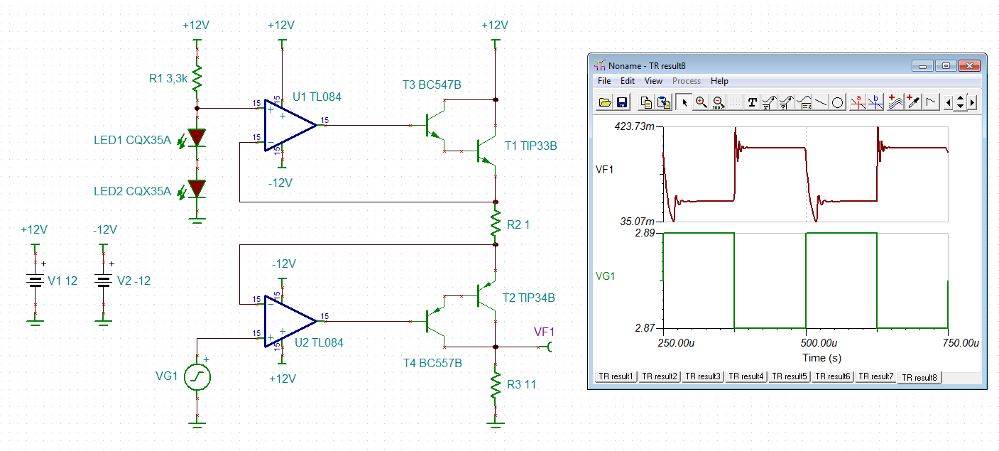
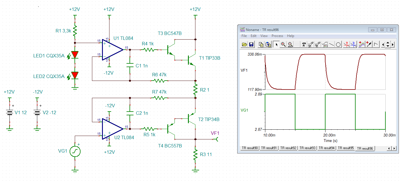
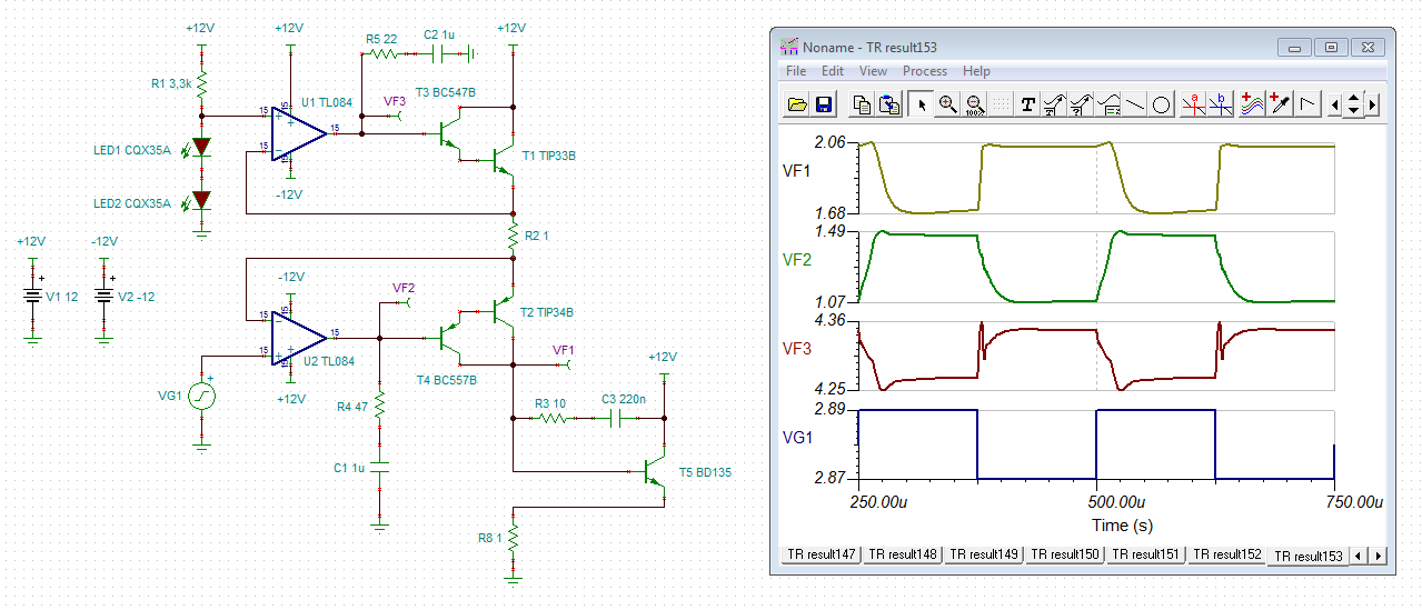
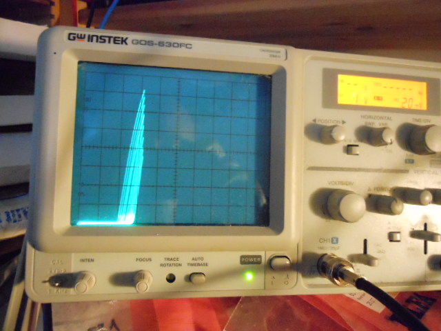
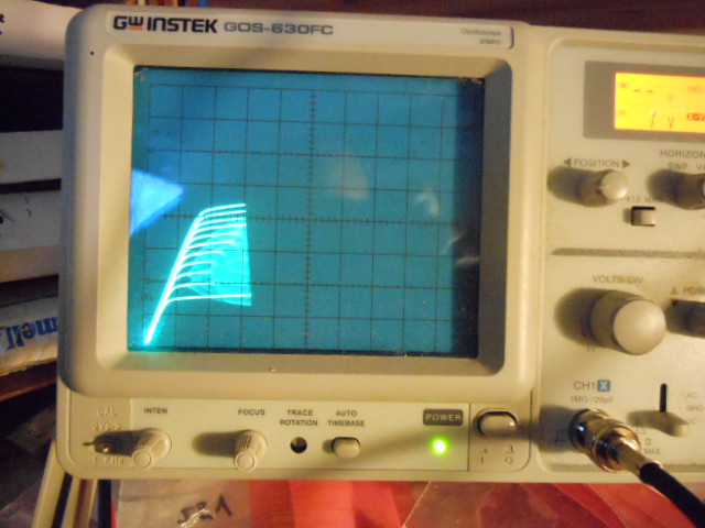
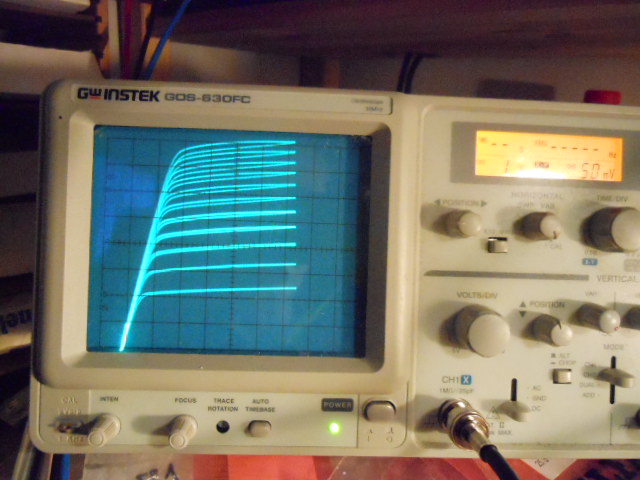
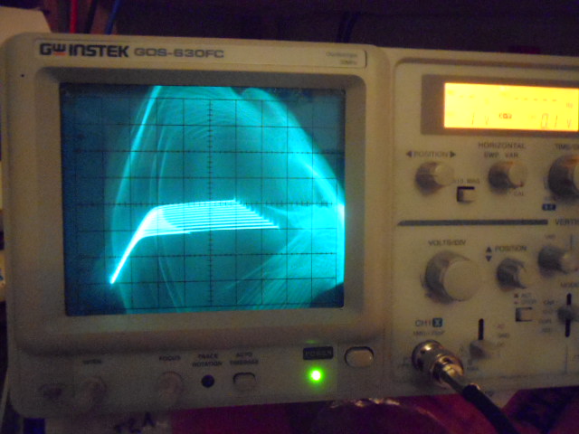
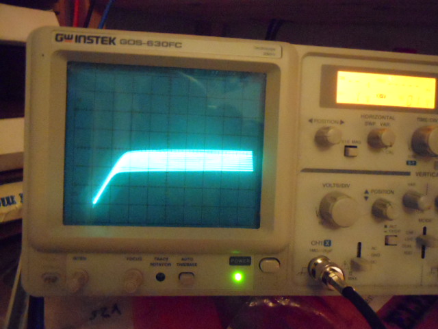
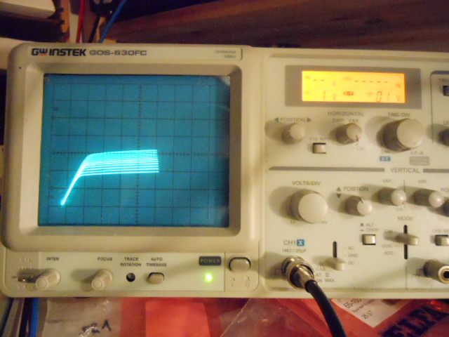
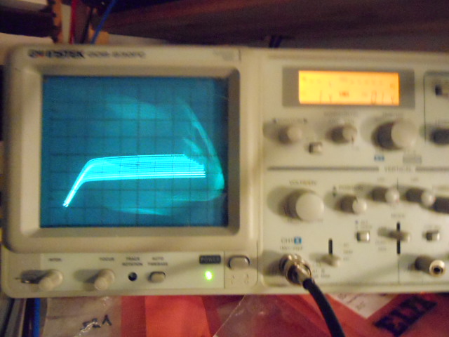
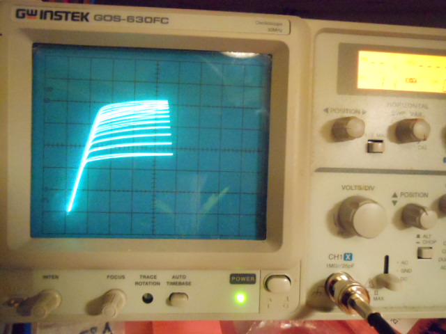
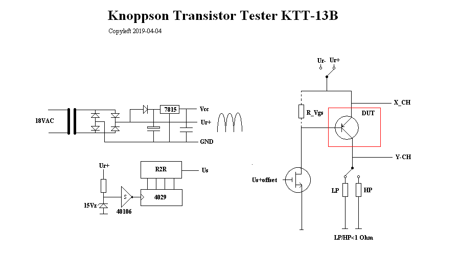
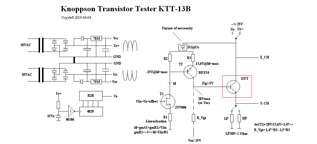
I am trying to build a transistor curve tracer but at some settings I get stubborn oscillations that I really can't get rid of.
I think that HF-oscillations should be quite "easy" to get rid of, it usually just takes a small capacitor at the right place.
However, I have tried for weeks now to find that certain place.
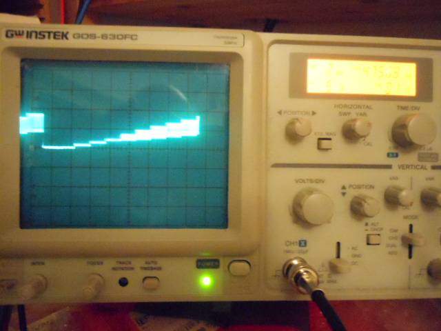
The oscillations occur at Ub (and actually almost everywhere but it is there I measure it).
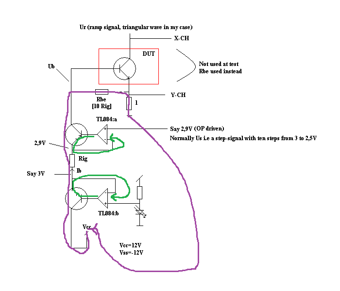
Now, using a Rig of 1k makes things work without oscillations but using Rig of 1 Ohms makes it oscillate.
I really need 1 Ohms to be able to test high power transistors (up to 5 amps momentarilly is my thought).
So why does it oscillate with Rig of 1 Ohms and not with Rig of 1k?
I have almost given up on this project.
MVH/RogerPSTo me it seems like it is current dependent but how can a certain amount of current make things unstable?
I seem not to be able to move the picture to where i want it, I am bad with computers.
In reply to kai klaas69:
Regards,Ronald MichallickLinear Applications
TI assumes no liability for applications assistance or customer product design. Customer is fully responsible for all design decisions and engineering with regard to its products, including decisions relating to application of TI products. By providing technical information, TI does not intend to offer or provide engineering services or advice concerning Customer's design. If Customer desires engineering services, the Customer should rely on its retained employees and consultants and/or procure engineering services from a licensed professional engineer (LPE).
Hi kai!
I thank you very much for your clever tip, I was not in the vicinyty to think that way!
My problem now is that PCB is already finished and sitting there but here is the good thing, I always use sockets so I can remove the OP, bend up the legs in discussion and force a resistor+cap assembly!
I will do this in spite of the fact that two TL084 packages will have to be modified.
But this inspires me!
I do however wish that I understood what you are talking about regarding phase margin, I know what it means but I do not know how it works (BF>1@180deg is the oscillation criterium, right?)
Best regards, Roger
In reply to Ron Michallick:
Just wish to say thanks to your both, kai gave me a practical tip and you elaborated on the theoretical side. I like both types of encouragement even though I kind of prefere practical ones (but only if I have a practical problem). Best regards, Roger
In reply to Roger Knopp:
Thank you Ronald for your tip!
This procedure of course make it much easier for me.
It makes me able to not even have to remove the OPs but to solder the snubber on outputs to ground.
Today I prepared for lifting pins and using component adaptors but thanks to you I seem to not have to.
However, I really wished I understood what you say about zero and pole, I actually know what these things are (a pole makes the gain drop and a zero makes the gain increase) but I have not come to the competence like yours such that I understand how to use them, often I do not even understand in which direction phase is "moving".
If I use my incompetence I would say that your snubber loads the OP very little at frequencies slightly above DC and 47Ohm at HF, but how this can stabilize my OP is an enigma to me.
I will try this snubber asap, thank you very much for making it more simple for me!
Best regards, RogerPSI pushed the "This resolved my issue"-button yesterday because I thought the tip from Kai was very good but then I kind of regret "closing" the tread because I wish to show you my progress. Today when I see you guys talking to me in spite of this I got glad because perhaps I may show you my progress at a later date.
Hi Kai!
I liked this explanation very much, it almost made me fully undrestand.Actually, I used to think that an OP output is some 100 Ohms open-looped but gets very small when looped (due to voltage/parallell feedback).
I had some other stability problems too, a complementary power buffer (one polarity at the time, same project) oscillated but was cured by 100nF directly over output.
I have tried this with my latest oscillation problem but it has not worked, at one time I began with 100nF (Ker) and when it didn't work I increased to 1uF (polyprop) and when that didn't work i increased to 10uF (electrolythic) in pure desperation but of course it did not work.
I actually put these capacitors directly over the minus input of TL084:b to ground, thinking something like a 78-series regulator needs (or recommends to have) a 100nF over the output.
But it did not work and before your kind tips I was prepared to give up.
I will however try this snubber tonight, just stand by for results...
It did not work but I have only tried on one of the opamp and the oscialltions got better.
I recon I have to snubber both opamps to make it work, anyway here is what I tried: 100+100nF at output of TL084:b, when this didn't work I tried 10+100nF but this didn't work either exept that the amplitude got a little less.
Attaching two photos, the first is before any snubber and the next is with 10 Ohms/100nF.
Reading on oscilloscope shoud be a straight line at third DIV (1us, 1V/DIV@CH2 [10X Tek-probes is being used]).
Best regards, RogerPSFor this polarity, the frequency is down to some 700kHz.