This thread has been locked.

If you have a related question, please click the "Ask a related question" button in the top right corner. The newly created question will be automatically linked to this question.

Selection of OPAMP for narrow band Active band pass filter

Other Parts Discussed in Thread: TIDA-01036, TINA-TI, UAF42, OPA209, OPA211

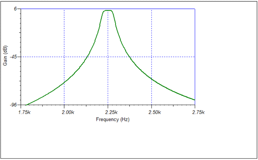
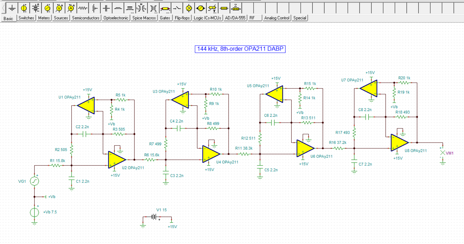
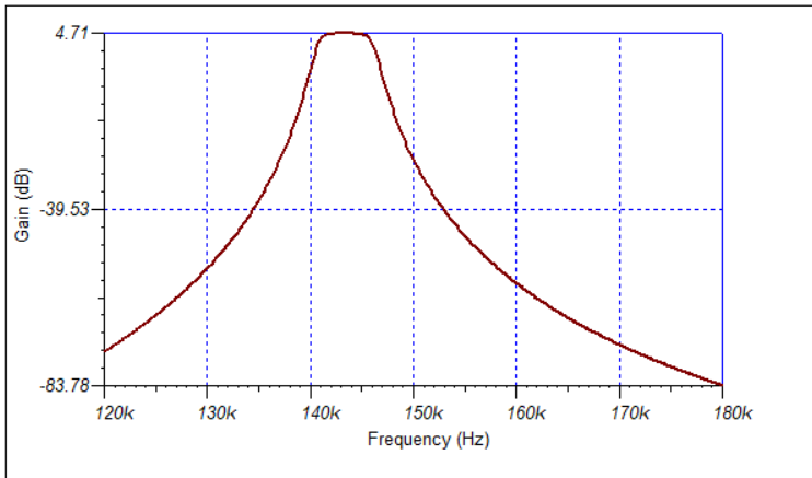
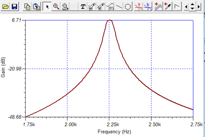
I design a narrow band pass filter using filter pro. I have selected the Multifeedback single ended, chebyshev filter, with order 8, stages 4 gain of 1.121 V/V central frequency fc at 2250 Hz, band width 50Hz. Kindly suggest me best Opamp for this design. Also as i used the single ended 10 stage opamp (OPA37E) based amplifier before this filtering stage so do i need to select single ended multi feedback amplifier or i can go with fully differential as like ( @TIDA-01036 High-Q Active Differential Band-Pass Filter Reference Design for Instrumentation Qualification). My design is attached kindly check in the attachment.

narroe band BPF filter pro.pdf

  • Hi Parag,

    the band pass filter shown in the pdf uses MFB band passes with a Q of up to Q=323. And you have four of these MFB band pass filters in series. Sorry, but such a high Q is totally unrealistic! This MFB band pass filter type is ideal for a Q of up to Q=5 and can only be used for Q<25, if at all. But a Q of Q=323 is entirely unrealistic.

    There's a rule of thumb that the open loop gain of OPAmp must be at least 20 x Q^2 at the center frequency. This would mean an open loop gain of 126dB at 2250Hz. So, you would need a 5GHz OPAmp to fullfill this need...

    Another issue is manufacturing tolerances and drift of filtering components. Even the least mismatch of components and the unavoidable temperature and long term drift will totally ruin the frequency response.

    Have you already simulated the circuit with TINA-TI?

    Kai
  • Hello kai,

    Thanks for this information. I have not simulated the circuit yet. I made certain changes suggested by you in filter pro and make sure that Q factor will lie within the range but still not getting the desirable results. As far as designing the narrow band pass filter is concern anyway, Q must be greater than 10. In that case which type of filter design i should use ?
  • Hello Parag,

    Kai has explained well the issues with attempting to realize a very high-Q band-pass response. You can see from your original FilterPro printout that the individual stage Q values were running about 133, which the standard single op amp Multiple Feedback (MFB) and Sallen-Key filter topologies can't realistically achieve. It is often recommended to keep the stage Q to a maximum of 10 for the MFB, and about 25 for the Sallen-Key, providing moderately low stage gains are used.

    Most often, when very high-Q stages are needed in a filter a state-variable analog filter topology is used. The topology utilizes 3 op-amps for each 2nd-order stage, and because of that much higher Q can be supported. TI offers the UAF42 Universal Active Filter and likely could meet the requirements for a 1 dB, 2.25 kHz fc, 50 Hz BW, Chebyshev filter. You may want to have a look at its datasheet:

    I did look for a simpler approach to your filter requirements and tried simulating some different filter topologies. Interestingly, a variation on the MFB that incorporates a degree of positive feedback produced a pretty accurate response. You will find the schematic for the filter as follows:

    The filter has a center frequency of 2.25 kHz and a gain of 1.58 V/V (4 dB), and the bandwidth is close to 50 Hz. I used OPA209 op amps having a unity gain-bandwidth of 18 MHz. The op amps need to have a gain-bandwidth of at least 15 MHz to minimize distorting the response. The one characteristics that is missing is the ripple in the passband associated with the 1 dB Chebyshev filter. I've found that to capture the filter ripple the op amps must have very high gain bandwidth in the hundreds of Megahertz, or even in the Gigiahertz.

    Unfortunately, high-order filters such as this 8th-order filter are extremely sensitive to component values. I provided exact values for the resistors and capacitors. If they are off from the ideal value by a fraction of a percent, the response can be badly altered. Precision resistors are available, but precision capacitors are harder to come by.

    Alternately, I recall there being a two op-amp per stage filter topology that supports high-Q filter band-pass responses in a handbook. I am traveling for TI right now so I don't have access to the Electronic Filter Design Handbook, by Arthur Williams, but I do believe that is where I came across it.

    I attached my TINA Spice circuit for the 8th-order band-pass if you would like to try it.

    OPA209_BP_8th_Ord_01.TSC

    Regards, Thomas

    Precision Amplifiers Applications Engineering

  • Hellow Thomas Sir,

    Thank you for the detailed information. I have arranged that book which you mentioned above and will refer for my broadening my knowledge in this topic. I have gone through with your all suggestions and made corrections accordingly. As far as UAF42 is concerned, I have tried that also with my preamp but i am unable to get the desired response (may be i am unable to get the right combination of resistors and capacitors for my filter). Also i have tried the above schematic with circuit and this looks perfectly fine with it. Now my doubt is regarding its tolerance limit which you highlighted, that small change in component value may result badly on performance. How would i make more robust and tunable.
  • Hi Parag,

    eventually a state variable filter could do the job. It has been discussed in this thread:

    e2e.ti.com/.../2845968

    Kai
  • Hello Parag,

    Now that I am back in my office I have access to my Electronic Filter Design Handbook, that I mentioned previously. The High-Q band-pass topology that I was thinking about is covered in the Bandpass Filters Section, under the Title, "Dual-Amplifier Bandpass (DABP) Structure." The information indicates that it is usable with Qs up to 150, the Qs are easily adjustable, and component sensitivity is small. The handbook walks you through the design process. It references filter tables that the book includes and provides the equations you will need to apply.

    Some time ago, I designed a high-Q 144 kHz bandpass filter for another customer. I have copied an image of it, an 8th-order DABP below so that you can see what a complete filter looks like created from the handbook information.

    Regards, Thomas

    Precision Amplifiers Applications Engineering

  • Hi Thomas sir,

    I got the book and that is so informative. I think that, this will solve my problem too. I'll get back to you after completing the circuit. Thanks a lot for the help.

    With regards
    Parag
  • Hello Parag,

    Smart decision to get the Electronic Filter Design Handbook. It is my "go-to" book when one of TI's active filter design programs doesn't quite have what I need. I have designed many filters based on the information that it provides.

    If you do need help selecting op amps for the finalized filter do drop us another e2e post. If for now you can close this e2e inquiry that would be helpful to us.

    Regards, Thomas

    Precision Amplifiers Applications Engineering

  • DBAP.TSCHello Sir,

    I have designed one similar design as you mentioned above. Kindly see the schematic and help me to improve it if you found some mistakes.

  • Hello Parag,

    I reviewed your DBAP filter and its response certainly looks like that of a narrow bandwidth bandpass filter. When I simulate your TINA Spice file I find the filter has an fc = 2.25 kHz, a gain of 6 db (2 V/V), an fl (-3 dB) of 2.213 kHz and an fh (-3 dB) of 2.292 kHz. That results in a -3 dB bandwidth of 79 Hz, and an overall filter Q of 28.5. I am not sure what response type you selected, but possibly a Butterworth. If these are the design goals you had in mind, then the filter should do what you need.

    It looks like you are applying the DBAP design procedures provided in the filter handbook correctly.

    Regards, Thomas

    Precision Amplifiers Applications Engineering

  • Hi sir,

    I have designed that filter keeping Q approx to 70 and pass band bandwidth of 50Hz but i think above response will also work for me. Can i lock this Opamp for this design ? Also Can i send you my complete circuit in mail ? Apart from this, it looks like i got what i wanted. Thanks for your help. 

    With Regards

    Parag

  • Hello Parag,

    The OPA211 is a good choice for the op amps in this DABP filter. It is has a unity gain frequency of 45 MHz, which helps assure you will get an accurate filter. response. I suggest using 0.1 % resistors, and the lowest tolerance capacitors that you can justify buying. Inaccurate component values can cause the filter response to be distorted from ideal.

    I would like to see your final filter circuit, but really need to move on to the many other e2e inquiries that customers need assistance with. Therefore, if this inquiry can be finished and closed that will help me to assist them.

    Regards, Thomas

    Precision Amplifiers Applications Engineering

  • Hello Sir,

    Perfectly fine. It was great learning discussion with you. I compare the result with UAF42 as earlier mentioned by Kai sir but got more accurate result in this design (DABP).

    Thanks for your support thomas sir and kai sir.

    With Regards

    Parag