This thread has been locked.

If you have a related question, please click the "Ask a related question" button in the top right corner. The newly created question will be automatically linked to this question.

INA193: INA193, LT1013

Other Parts Discussed in Thread: LT1013, OPA237, INA193, LMC6001

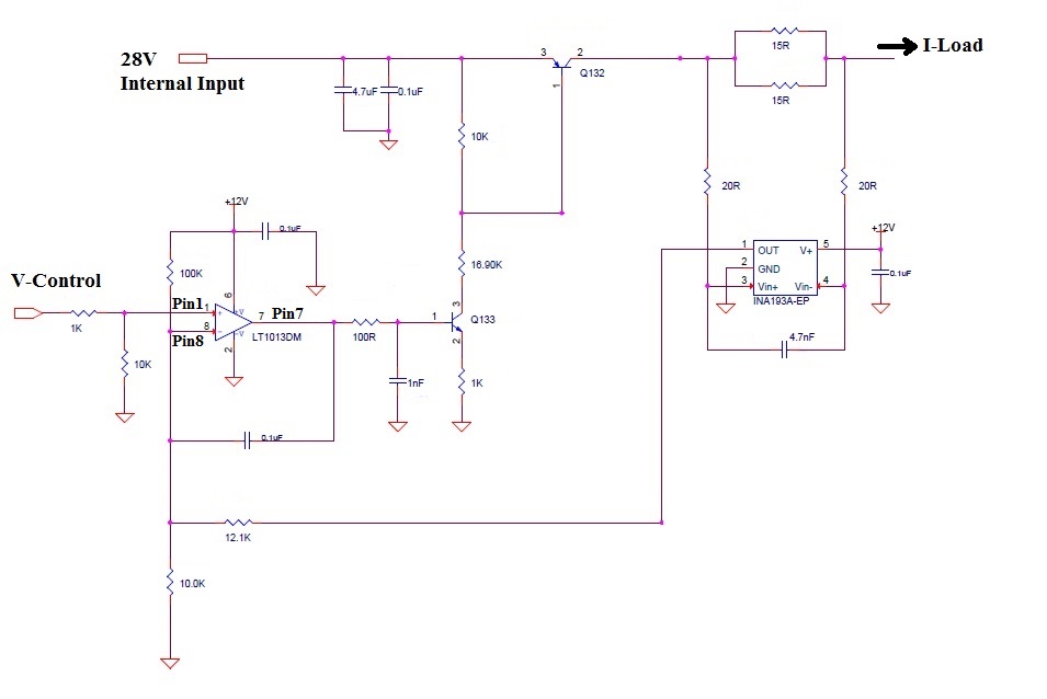
I have the attached circuit as a Voltage Controlled (V_Control) Current Source (I-Load).

This circuit has an stability issue. When V_Control drops from 3.3 V to 0 V the circuit works fine at room temperature. But when the temperature is reduced to -45 degrees, it starts to oscillate.

I cant figure out why? I have kept asking this on TI forum and these are the possible reasons:

  1. Slamming on the rail of LT1013 causes the pole in its output stage move to left reduce phase margin

  2. OPAMP has multiple loop feedbacks and the delay on Q133, Q132, INA193A increases during transition


Please see the attached waveforms.


At room temperature:
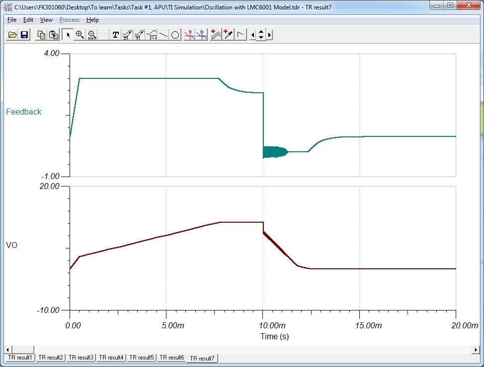
 At -45 degree C:

We have been able to resolve this issue by removing integrator capacitor (0.1 uF) between pin 7 and 8 of the OPAMP. Here is the measurement with no cap:


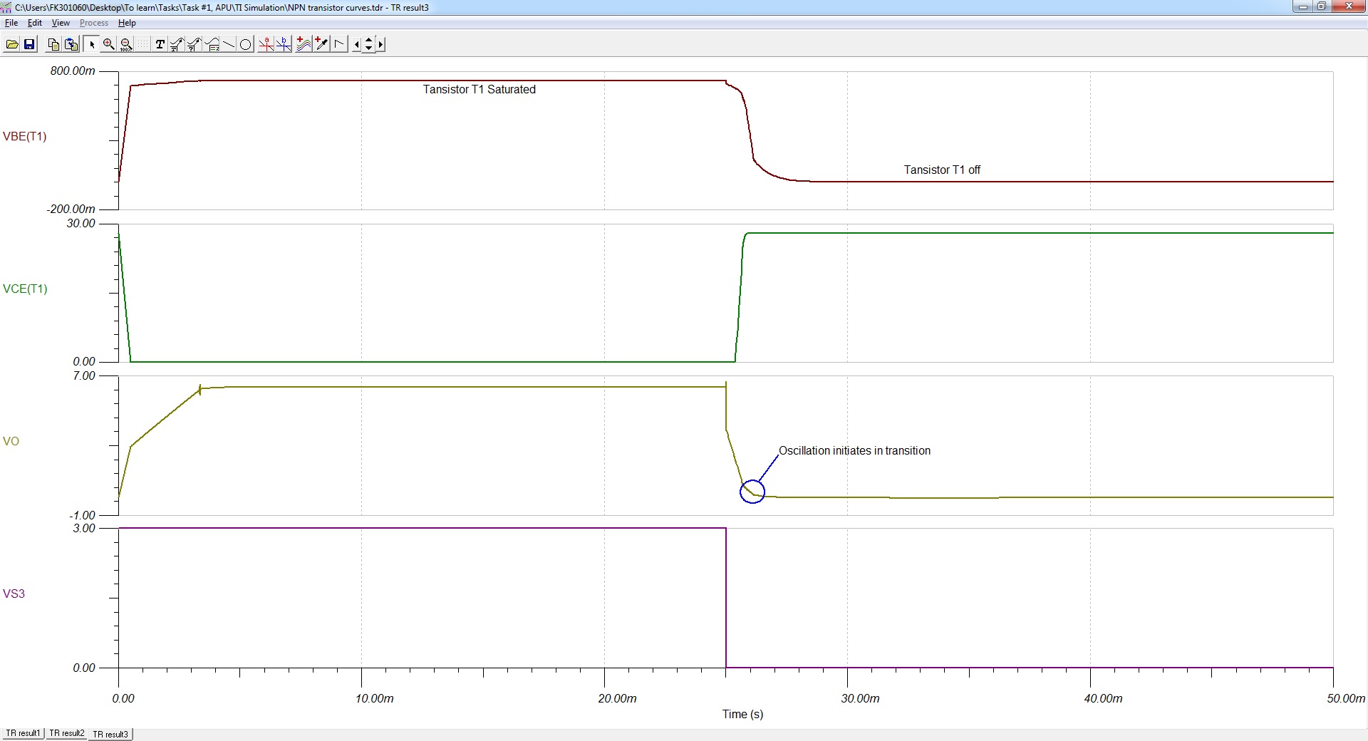
Time domain simulations show that Q133 is saturated when V_Control is 3 V and it is off when V_Control is 0 V. So I have difficulty simulating the overall loop gain of the circuit as the oscillation happens during transition when Q133 is coming out of the active mode and turning off (VBE pumping current out). Please see bellow is the NPN and PNP behaviours during the V_Control signal transition from 3V to 0V. (in this simulation OPA237 model is used)


Tina Simulation File:

Simulation Explanation.TSC

 
I am trying to justify either with calculation or simulation.

Please let me know if you have ideas that can help specially with the simulation.

Thanks

  • Hi Kaveh,

    the "V-control" voltage range is 0...3.3V? And the "I-Load" shall do what in this range? What loads are connected to the "I-load" pin? Is it only resistive or can it be capacitive or inductive? What is the "V-control" signal looking like? Is it a DC-voltage or a AC-voltage waveform?

    Kai
  • Kai, V_Control is a step signal from 3.3V to 0V. Load is variable normally 2K ohm but oscillation has been seen when the load is reduced to 600 ohms. The circuit is a voltage controlled current source. It applies 28 V to the load buy the control of the input V_Control. The load is only resistive.
    V_Control in the attached figures are U89-pin1. And pin8 and pin7 are the opamp negative pin and output pins.
  • Hi Kaveh,

    what is the period of the step signal? What is the slew rate of the step signal?

    And what is the "I-load" current range? 0V at "V-control" means what current? 3.3V at "V-control" means what current?

    Kai
  • Input V_Control signal is a single step that makes the circuit unstable. Please see the waveforms in the post. The middle black background waveform that shows the oscillation. I do not know the slew rate of the input, but lets assume infinity for now.
    0 V at V_Control causes the circuit shut off and do not deliver any current to the load. Iload = 0
    3.3 V at V_Control means circuit is active and input 28 V is put on the load. I load = 28V/ RLOAD. Example: V_Control = 3.3V , RLOAD=2K => Iload = 28V / 2K = 14 mA
    When Vin = 0V or 3.3 V OPAMP is in the non - linear mode.
  • Hi Kaveh,

    if the OPAmp is in non-linear mode, why do you need the INA193 then? Your circuit is a simple electronic switch which connects and disconnects the Rload to and from the 28V supply voltage? That's all?

    Kai

  • In linear mode, this circuit is a voltage controlled current source. I_load is defined by V_Control as I_Load = a. V_Control + b
    In this mode, INA193 reads the output current and compensate if the load is changed to keep the current constant.
    But this oscillation happens when there is a switching driving the opamp in the non linear mode.
  • By using LMC6001 model I can see some Oscillations in transient simulation.

  • Hi Kaveh,

    and what is "a" and what is "b"?

    I asked you how the "V-control" signal looks like and you said that the "V-control" steps from 3.3V to 0V and that the slew rate is infinitely fast. So, your OPAmp will never work in the linear range at all.

    Sorry, Kaveh, but all this makes absolutely no sense to me.

    Kai
  • Hi Kaveh,

    The CMOS LMC6001 op amp has a very different design than the bipolar LT1013 op amp. The output stage designs are completely different and will exhibit very different complex open-loop output impedance (Zo). That and the open-loop gain/phase (Aol) characteristics are key op amp parameters affecting stability, in addition to what is connected around them in the circuit. This assumes that the op amp is being operated in its linear input and output operating regions.

    If the input common-mode voltage range is exceeded the electrical parameters may be badly degraded. If the output is pushed into saturation the electrical parameters the op amp stops functioning as an linear amplifier altogether.

    Regards, Thomas
    Precision Amplifiers Applications Engineering