This thread has been locked.

If you have a related question, please click the "Ask a related question" button in the top right corner. The newly created question will be automatically linked to this question.

OPA211: Problems with Shutdown Pin

Part Number: OPA211

Hi,

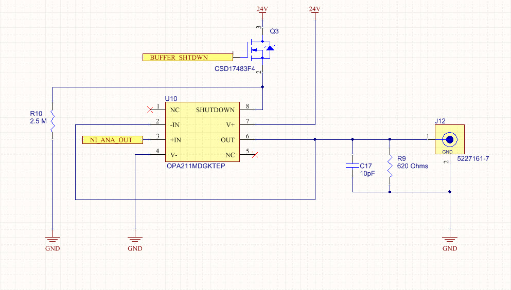
I am trying to get the OPA211MDGKTEP amp to work as a unity gain buffer with the Shutdown signal as an enable. The application is pretty simple, I run my signal (1kHz 1Vpp 1.5V offset sine wave) into the + of the op amp with the output tied to the - and a R load and C load of 620 Ohms and 10 pF, respectively. The rails are tied to 24V and 0V. The shutdown Pin was attached to a pulldown resistor and the source of a transistor but that transistor proved to not be biased properly so it was taken off entirely. 

The shutdown pin seems to output a voltage from the chip at around 19.5V if measured while floating. Attaching 24V to the shutdown pin does not cause the output to turn off. Just to try, we tried to attach 30V to the shutdown pin to see what would happen, and the power supply output hit the set current maximum of 200mA and dropped 26V. I would have imagined this pin to be high impedance so we thought this was strange. Pulling the pin to ground also does nothing, as expected.

The component markings show "1125 OBCM". I have confirmed the footprint, connections, and orientation of the component. We are trying it on a PCB so though we have tried this across multiple components, their implementation is identical. 

We figure something is wrong here because this seems like it should be an easy implementation. If anyone could help us shed some light on the problem, let us know.

  • Hello Kanan,

    Lets examine this a section at a time.

    The shutdown pin seems to output a voltage from the chip at around 19.5V if measured while floating. - The OPA211 is not intended to have the enable/shutdown pin float as stated in datasheet Section 7.4.1

    - This pin must be connected to a valid high or low voltage or driven, and not left open-circuit.

    Attaching 24V to the shutdown pin does not cause the output to turn off. Just to try, we tried to attach 30V to the shutdown pin to see what would happen, and the power supply output hit the set current maximum of 200mA and dropped 26V. I would have imagined this pin to be high impedance so we thought this was strange. Pulling the pin to ground also does nothing, as expected.

    - The OPA211 normally goes into shutdown mode when a valid high voltage level of (V+) - 0.35 V to (V+) is applied to pin 8. It is a high impedance pin within its specified operating voltage range. If 30 V is applied to pin 8 when V+ is 24 V, an internal ESD protection diode connected between pin 8 and V+ may become highly forward biased. The diode in only rated at 10 mA and it is possible that it would be damaged by the event if the current becomes much higher than the rated maximum. That event would likely damage the OPA211 enable/shutdown circuitry as well. The datasheet Section 6.1 Absolute Maximum Ratings lists the maximum Input voltage (V–) – 0.5 and (V+) + 0.5 V.

    The component markings show "1125 OBCM". I have confirmed the footprint, connections, and orientation of the component. We are trying it on a PCB so though we have tried this across multiple components, their implementation is identical. 

    - I do need to see how the "1125 OBCM" is marked on the devices. I do not have access to detailed lot code information, but I do know what the marking arrangement is supposed to be. Please capture some images of the OPA211 device markings and post them here as an e2e response.

    Note that the OPA211MDGKTEP is an Enhanced Product, OPA211-EP, produced by another organization within TI. If it turns out there is an issue with the devices the Enhanced Product group will be the one to assist you in obtaining a resolution. 

    Regards, Thomas

    Precision Amplifiers Applications Engineering

  • Hi Thomas, thank you very much for your response.

    My apologies, I thought I had seen 1125 but it apparently says T125. 

    The Pin was only left in an open circuit temporarily, we asserted the 24V for the valid V+ signal and did not see the expected response. The output would momentarily stutter (this could have been just the oscilloscope adjusting) and lose some of its DC offset but the AC signal would still propagate through with no problem.

    When we placed 30V onto the pin, we did not use that unit for further testing. I would not doubt that it fried something internal to the chip, we just wanted to see if maybe somehow our expected V+ signal on the shutdown Pin was somehow not asserting the shutdown state.

    Is this Enhanced Product group a separate forum?

    Best,

    Kanan

  • Hello Kanan,

    Thank you much for the image of the OPA211MDGKTEP device. I am trying to find someone in TI's Enhanced Products group that assist you with this issue. Since that group is in a different time zone, they wouldn't be available at this time of the day. I will make some calls tomorrow and see who I can find to assist you.

    Regards, Thomas

    Precision Amplifiers

  • Hi Kanan,
    I am not that clear on all your trouble shooting techniques. Have you tried a new unit (one that has not been powered up yet) on your modified board with the transistor removed?
  • Yes, I tested this on two different boards, ie two different chips. With one, i was not gentle and probably fried it looking at the 30V response. The other, I never tried more than 24V and 0V. They both produced the same response on the output which I described in my second post.

    I'm going to order some more of these chips and bread board them for a sanity check but this problem is pretty strange. I, personally, can't think of a reason why this wouldn't work.

  • Hi Kanan,

    My concern was that you mentioned that the transistor on the board was configured the wrong way.   I was wondering if you had put power to your boards when the transistor was in place and that error caused damage to the units on the boards.   That is why I suggested replacing he unit with a new one. 

    We do not see any issues with your schematic and the behavior you describe sounds like a damaged part, but could be an issue with the board.

  • Right on. I'll try bread boarding it and see what happens.

    Is there any information on the impedance of this pin? I'm confused how connecting a voltage to it would cause it to break unless it has a low impedance.

    Thank you all for your help by the way.
  • Hi Kanan,

    The pin will be high impedance but I don't have an exact value. I don't have a part to measure or the internal schematic of the part, but typically the part will remain high impendance unitl you turn on the ESD diode. At room temperature, that is typically 0.7V above the supply voltage. Current increase will be exponential with voltage was the diod is turned on.