This thread has been locked.

If you have a related question, please click the "Ask a related question" button in the top right corner. The newly created question will be automatically linked to this question.

INA282: INA282 for battery test equipment

Part Number: INA282

Hi,

customer use INA282 with VSSOP package in high precision battery test equipment,and have a problem about the output voltage. the schematic as below, current sense resistor is 0.01ohm.

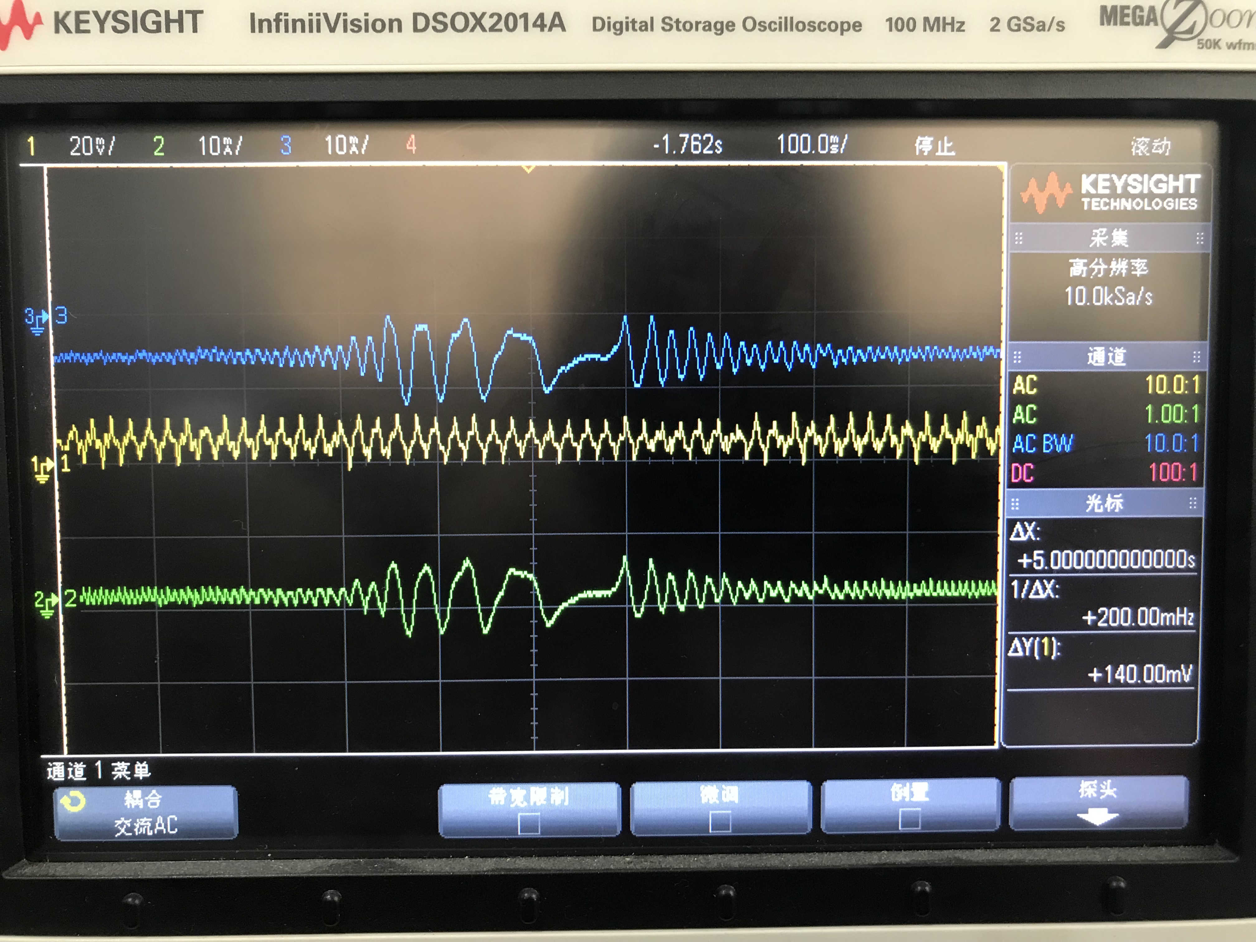
During the battery charge and discharge, current has a large ripple, while the output voltage not follow the current change. It is a close loop in their project, ADC will sample INA282 output voltage as feedback to adjust current. It will be lost control if output voltage of INA282 not follow current change.

test result as below: green is current of sensing resistor, yellow is output voltage of INA282 and blue is the current of BTS output.

1. if we use INA282 with SOIC package, there's no this issue. what' the difference between SOIC and VSSOP?

2. we removed the R114,R116,C42 and C41, result is the same. Using a dryer to increase the temperature of INA282 or use FAN to cool down, the issue will be recurrent. is there any design consideration about temperature?

could you help on it? many thanks in advance.

  • Hello Betty,

    Thanks for reaching out on the forum. I think the difference in performance could be byproduct of manufacturing tolerance and temperature and not due to a different package. According to what I see you are looking for a signal that at max is 10mA pk-pk centered around 0A. This means the input voltage difference between IN+ and IN- of the INA282 would be 0.01mohm x 0.01A/2= 50uV at most. If we look at the electrical characteristics table of the INA282 datasheet we can see that the offset voltage referred to the input typically is 20uV, but can be as high as 70uV. To actually see some meaningful change on the output, your input signal needs to be larger than this offset. As our available devices' performance will fall under a gaussian distribution related to the specs found in the EC table, your VSSOP devices likely had a higher than 20uV offset while the one SOIC you tested likely had a lower than 20uV offset. Also the temperature your test system was in would also be an important factor with such a small signal. If your VSSOP was tested in a hot room while the SOIC was tested in a cold room, the SOIC would more likely have a lower offset and therefore perform better. If your customer wants to measure this signal, I recommend using a larger shunt resistor.