This thread has been locked.

If you have a related question, please click the "Ask a related question" button in the top right corner. The newly created question will be automatically linked to this question.

THS4551: Need help understanding design problems

Part Number: THS4551
Other Parts Discussed in Thread: NE5532, TL082, THS4531, ADC161S626

Hello everyone, I'm writing this because I've tried to understand why some things were happening when simulating a design and I've not reached a definite conclusion on the problem. My best guess is something to do with the THS4551 specifications that I'm probably not seeing.

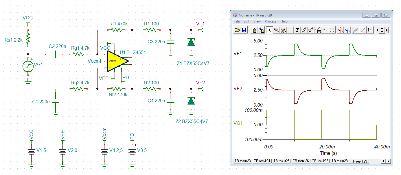
What I'm trying to accomplish is to amplify and filter a sound signal coming from an electret microphone as seen in the attached image. This signal is AC cuopled and then feed to the differential amplifier as a single-ended input, in order to apply gain and filter the frequencies I'm not interested in. The voltage generated by the mic is around 50-100 mV peak to peak.

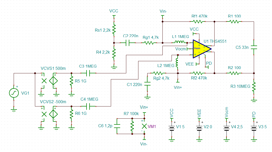
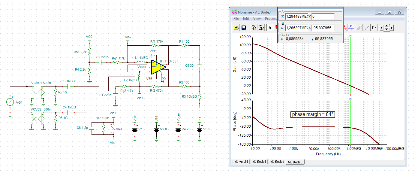
The bode curve that results from this setup does what I need, however, calculating the gain as Rf / Rg = 100, which would be 40dB, the bode doesn't quite get there (it's approx 26db).

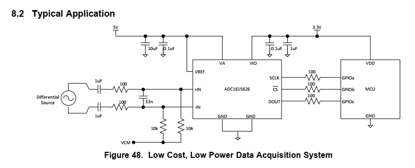
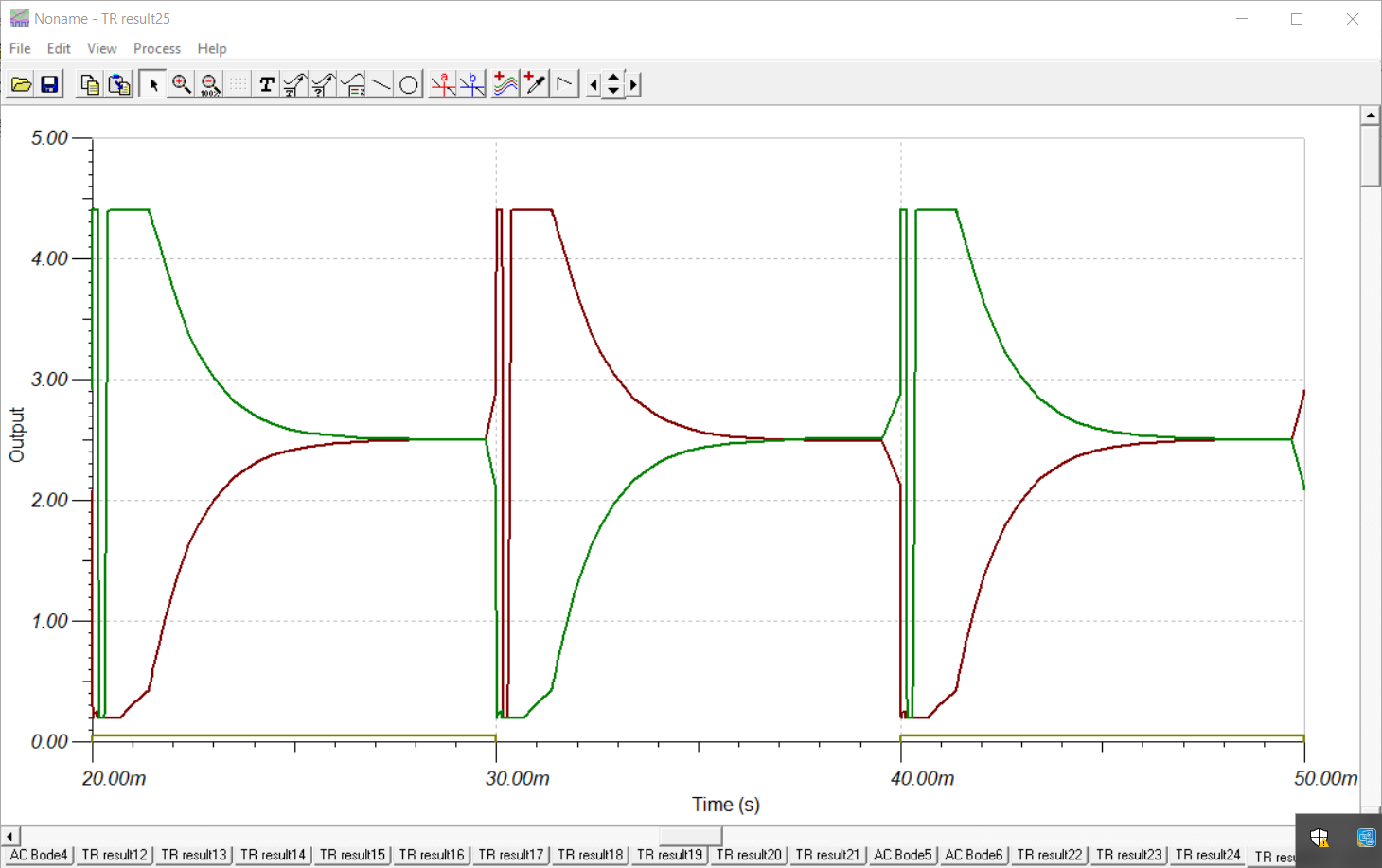
If I try to increase the feedback resistance Rf (or decrease Rg) and simulate the transient response of a squared-wave of 50Hz and A=50mV the circuit turns unstable (I think).

Note: The limit on the top and bottom are caused by the zener diode, this is on purpose to avoid any overvoltage going through and damaging the ADC. I'm fairly certain this shouldn't affect the performance but I added them just in case.

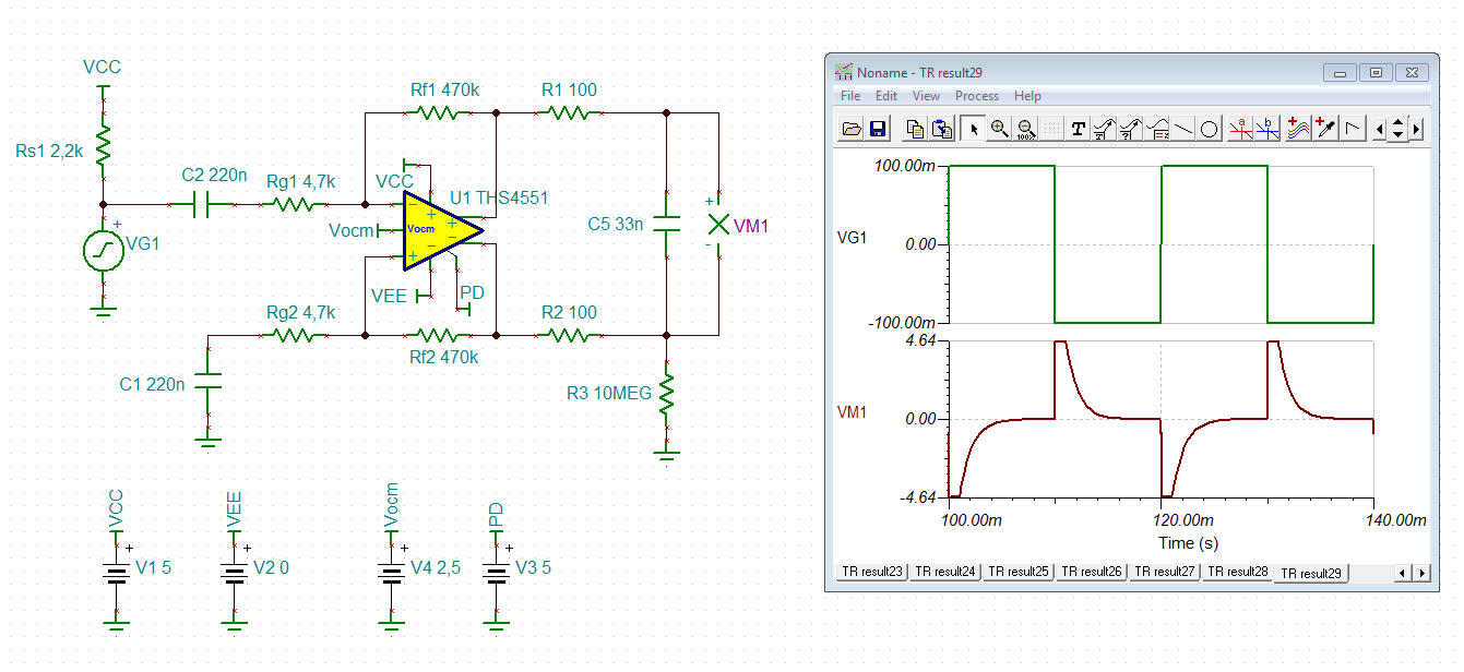
The output will be directed to a multiplexer and then an ADC, both differential.

One additional thing is that I simulated the Open-Loop Gain and there's approximately 80° of Phase Margin at around 800kHz.

So finally I don't know if I'm missing something but I guess asking wouldn't hurt.

If you need any more information I'll gladly comment further.

Thanks,

Santiago

  • Hi Santiago,

    your circuit is very unusual. Why do you use a 150MHz differential amplifier to amply a 50Hz signal from a electret microphone? Why not using a simple OPAmp for this?

    The 1W zener diode 1N3825 is short-circuiting the output of THS4551. This conflicts with the built-in short-circuit protection circuitry of THS4551. You need to increase R3 and R4 (R1 and R2 in my simulation):

    santiago.TSC

    Kai

  • Hello Santigo,

    The reason your gain looks low is you are not probing differential across the output pins, if I do that with Kai's attached file I get 40dB gain. And yes, the resistors seem high and the protection zeners are not necessary as the device cannot produce more than 0 to 5V outputs.
  • Hi Kai, thank you for taking your time to answer.

    I have tried a few simple OPamps (namely TL082 or NE5532) and I got them working, but since I wanted the whole input path to be differential I assumed the best way was to use a FDA. Later I realized that I could have done it with two discrete amps, however that would rely on both sides having very precise values if I understand correctly, so in the end I tried with this one.

    I completely forgot to specify what frequencies I wanted to amplify, they are around 100 and 2-3 kHz, but you are right, maybe this is not the best approach, will take that into account moving forward!

    Anyways, I will follow your suggestion and Michael's to increase those resistances and eliminate the zeners, which actually makes sense.

    Finally another question: following Michael's comment, I assumed that since the positive and negative output go into both pins in the ADC I had to probe them separately, but now that he mentions it, the final gain will still be the differential gain of the amplifier, correct?

    Thank you both again,
    I don't know if you have anything else to add. If that's not the case, I'll mark this as resolved then.

    Santiago
  • yes Santiago, the ADC needs a common mode voltage controlled by the FDA Vcm input pin, but will only process differential signals. If you are probing the output make sure you isolate that probe C with small series resistors the probe point, say about 50ohm. You can probe each side seperately if you want to, but usually you do that as a differential probe. If you wanted to use a slower FDA, look at the THS4531. But still at a gain of 100, the 30MHz or so GBP for the THS4531 will end up being only 300kHz BW.
  • Hi Santiago,

    ok, when needing a differential output the use of a differential amplifier makes sense.

    Keep in mind that the datasheet of ADC usually recommends a certain input filtering (sometimes also called anti-aliasing filtering or similar). You should follow this recommendation. But make sure that the OPAmp can operate stably with these filter components at its output.

    What ADC do you intend to use?

    Kai
  • Hi Michael and Kai,

    Very well, will have that in mind, I probably will probe the differential output as well just to have a more complete analysis. Thank you

    Kai,
    Okay, I'm glad it makes sense then!
    Yes, I have studied that as well but I haven't calculated the equivalent impedance yet, which results from considering the ADC input and also the Multiplexer model circuit inside. That's my next step, once I have that I will add it in the circuit as an RLeq and Ceq.

    The ADC I was planning to use is the ADC161S626, which fits my requirements.

    And yes, I've read the datasheet pretty extensively and remember that I need to add a resistor and a C to make the antialiasing filter, though that would probably resemble what I already have in the diagram I posted as R3, R4, C7 and C2 (Sorry about the names, I didn't notice). For the implementation I should switch it so instead of both Capacitors going to ground, they are connected (with a value of C/2? or 2*C?).

    I'm probably going to use the ADC at a Fs of 250kHz, so now that I see the bode again I may need to decrease the pole frequency resulting from that low pass filter after the amplifier output.

    After all of that, I'll simulate again and see what happens, hopefully still stable :)

    Thanks again,
    Santiago
  • Hi Santiago,

    then why not using the recommended scheme in figure 48 of datasheet of ADC161S626?

    And you can even omit the VCM offsetting scheme consisting of the two 1µ caps and 10k resistors at the input of ADC161S626, if the output signal of your THS4551 is already centered arround a suited 2.5V common mode voltage.

    Kai

  • Looks acceptable. Eventually, add 4.7p caps across Rf1 and Rf2 to improve the noise margin. As the feedback resistances are unusually high for the THS4551 and are far away from the recommended 1k (see table 5 of datasheet), still carry out a phase stability analysis though.

    Kai

  • Hi Kai,

    Man, I have seen that picture so many times I don't know how I didn't think about that.

    Truly amazing, I have followed your changes and performed a quick phase margin calculation and it is exactly 45º.

    Now the problem is that the 0db-cross is close to where all the phase shift happens related to the poles of the amplifier, so a slight variation in the value of the capacitors parallel to Rf1 and Rf2 would mean a big shift in phase.

    From a few tests, I get the picture than I can't use any cap above 4.7p since that would be working within marginal stability, and the frequency of the pole is around 72kHz. Now if I use a 2.2pF cap, that frequency becomes 153kHz but on the plus side the phase margin is 60º approx.  I could even stretch further and use a 1pF cap to get an 88º phase margin, with frequency 338kHz.

    Simulation with C = 4.7pF

    Simulation with C = 2.2pF

    I may need some insight wether it's fine to just attenuate everything above 338kHz or I need to compromise a bit of margin and get a better attenuation in lower freqs, thus improving noise performance I assume?

    Regards,

    Santiago

  • Hi Santiago,

    here you see my phase stability analysis of your circuit:

    santiago2.TSC

    The phase margin is 84° which is pretty much perfect. And it turns out that adding 4.7p caps across the feedback resistors is no good idea.

    See also this:

    training.ti.com/ti-precision-labs-op-amps-fully-differential-amplifiers-fda-stability-and-simulating-phase

    Kai

  • Hi Kai,

    Thanks for the link, I actually followed that video to calculate the phase margins I talked about in my previous comment, sorry for not uploading the circuit, I'm new to this forum!

    But it's good to see that I was on the right track there.

    I think you covered everything I was uncertain of, thank you so much for all the help, I hope I wasn't too bothersome!

    Santiago

  • Not at all. It was just fun. :-)

    Kai