This thread has been locked.

If you have a related question, please click the "Ask a related question" button in the top right corner. The newly created question will be automatically linked to this question.

LMH6518: LMH6518 interfacing to THS4541

Part Number: LMH6518
Other Parts Discussed in Thread: THS4541, , ADS4245, VCA824, LMH5401, OPA859, ADS4225, THS3217, OPA656

Hi,

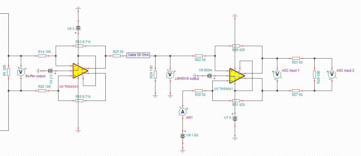
I am building a differential probe and a scope with ADS 4225. I am willing to have the LMH6518 inside the probe so that it is very close to the input buffers. My thoughts are that having the DVGA away from the buffers would introduce higher noise susceptibility due to the coaxial cable(s) connecting the buffers output to the DVGA. Now, if i do keep the DVGA close to the buffers (inside the probe), i would have to connect its' output to the THS4541 (ADC driver) input using 2 different coaxial cables so that i can keep the connection differential. However, i was thinking that after the DVGA, no significant gain would be necessary and thus using single ended connection would still be acceptable. In order to use single ended connection, i would have to use only one of the LMH6518's outputs, pass it through a 50Ω coax cable and terminate it with a 50Ω resistor right at the THS4541's input.

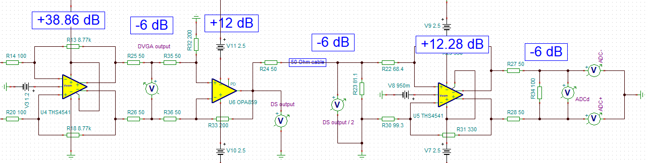
I have implemented a simulation circuit that has the buffers followed by a THS4541 (instead of the LMH6518) and then followed by the THS4541 (adc driver). (The LMH6518 TINA spice model is not available yet.)

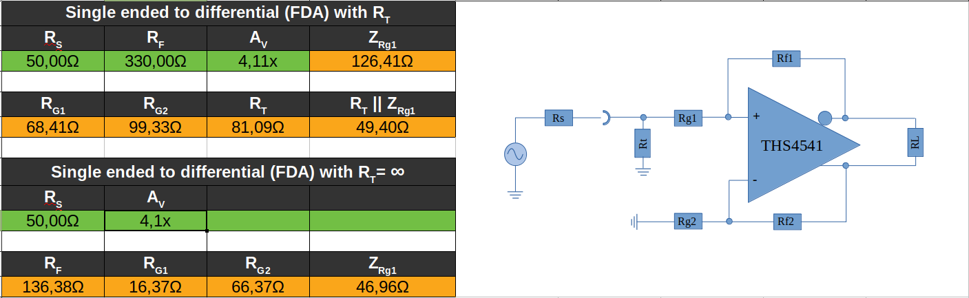
The point where i have my doubts is the value of Rt which in conjunction with the Rg1+Rg2 must be 50Ω. The output CMV of the first THS4541 (replacement of the LMH6518) was set to 2.5V. However the voltage value at the point where Rt & Rg1 connect is now not 2.5V since the Rt form an attenuator with the 50Ω resistor internally in the LMH6518. Rg2 had off course to be biased to the same CMV that the Rg1 was so i used the 1.65V that you see to zero the output (diff) of the THS4541 on the right.

The snapshot of the TINA TI schematic works fine. I set the CMV of the THS4541 to 0.95V as the ADS4245 requires and i get the expected amplitude at the output.

Can you pls confirm if using such a connection between one of the LMH6518 outputs and one of the THS4541 is an acceptable way of connecting the two opamps?

I think there is something wrong in the Rt value. Its' value would be correct if the Rg2 was connected to GND but Rg2 is instead connected to 1.65V! Wha should i do there?

Any suggestions regarding the schematic?

Regards

Manos

  • Hello again Emmanouil,

    Those Rt and Rg1 and Rg2 are in the upper block diagram - yes a difficult problem I finally solved back in early 2013. The solution for Rg1 ends up being a quadratic to simulateously set the input impedance and gain. Part 1 here reviews older single to diff approcaches, while part 2 was the first publication of the design equations - those were AC coupled designs, but they apply to DC coupled as well. Also shown in part two is pretty powerful active balun approach where you essentially solve for Rg1=infinity, which then gets the best noise

    www.edn.com/.../Wideband-matched-input-impedance-with-ultra-low-noise-using-the-active-match-capability-of-a-new-type-of-amplifier--part-1-of-2--

    www.edn.com/.../Wideband-matched-input-Z-using-active-match-and-a-new-type-of-amplifier--Part-two-of-two-

    Those design equations and discussion were repeated in section 9.4.13 in the THS4541 data sheet, but some summary comments

    1. You don't need to provide DC bias on the non-signal input side of the receiver FDA. Just ground it. The CM loop will find the right output voltage but the source will need to supply a DC levelshift current.
    2. If the cable is not going to be opened, you could eliminate Rg1 and get the pure active match as described in the articles. Including Rg1 will limit output fault voltages if the cable is opened up
    3. driving single ended out ofthe LMH6518 will save a cable, but you you might lose signal integrity. Basically, a lot of time each side of the output might look a little distorted, but the differential cancels that out. that will not show up in the model - if there was one. Sadly, for best signal integrity and one cable, you might have to go back to single ended for line driver. Not necessarily for sure, but something to consider.
  • Thanks Michael,

    I definitely need to do more reading! I will get it done. I knew it was going to be difficult. I have always been challenging myself.

    The links you sent were really helpfull but i have to go through them again and again.
    Since this is a battery-based probe or so i wish :) i have found that the quiescent currents alone make this a very challenging task.
    I will try a differential to single ended opamp after the LMH6518 DVGA. That will probably let me do what i want.

    Thanks again for the time you took to answer to my post.

    Regards
    Manos
  • No problem Emmanouil, these questions are right down my line. 

    Again, the LMH6518 might be fine using just one output to drive the line, If we care a lot about HD, probably not. The product group might know if you described your signal characteristics (time domain to 10Bits?? or something like that). 

    If you wanted to consider an adjustable gain diff to single, look at the VCA824 (there are 4 versions in this family) - might not be good enough on noise, 

  • Hi Michael,

    I struggled a bit with the formulas of the links above. I made some excel sheets and added these formulas.

    I prefer omitting the Rt which makes things a little easier. So using the equations in this link results in a match which is great!

    Using however the equations in this link where Rs, Rf, Av & Rt are all set by the user, resulted in cases where there was no impedance match.

    In the THS4541 d/s p39, 9.4.1.4 the ZA equation 11 calculates the impedance at the junction Rt/Rg1. Will this equation always calculate a matched impedance value if it uses the Rg1/Rg2/Rf values calculated by the equations (see first link) that do not use the Rt?

    Shouldn't i be measuring half the ideal source's voltage at the junction of Rs & Rg1 when there is a close match? That was the case with the formulas of the first link where Rt is omitted.

    Could you pls, just for making 100% sure that i get it, explain what a match is? My understanding is that an match is true when the Rs is equal to the common mode impedance (between Rg1 & ground) when off course we refer to single ended connections.

    Thanks & Regards

    Manos

  • Ok, here is some more

    Matched impedance means you are driving into a characteristic impedance cable (50ohm here) from a 50ohm source and would like to terminate the cable with the same impedance to avoid reflections. I guess you you could call that common mode impedance to ground. 

    Your original circuit looked like a gain of 8.4 - there will be a -6dB matching loss, so you can increase that gain if you want - if you run out of BW with the THS4541, the next big step up is the LMH5401. 

    With an Rt to ground, you can pick whatever for the Feedback R - it just needs to be large enough to give a solution. I worry about no Rt on the receiver board - what happens to the differential outputs if the cable is disconnected? 

    Here is some discussion and then an active match sim file.

    Matched input impedance FDA single to diff.docx

    Active input match with THS4541.TSC

  • Hi Michael,

    I can't begin to thank you. You have been a great help no doubt. I was wondering if you do private consulting. Here is my email: mail@naftilos76.com

    You are absolutely right regarding the omitted Rt thing. Since the cable is something that may occasionally get disconnected, i will face uncertain conditions. So i solved the equation (7) at p37 of the THS4541 datasheet for Rt and integrated it in the excel below. It turns out that the parallel product of Rt & Rg1 is not exactly 50Ω and i am not sure why it happens or whether it should be of concern. The same think happens on the lower Zrg1 cell calculated value (where Rt is infinite). What do you think?

    So i think that using an Rt at the input of THS4541 (adc driver) is, as you implied in your last,  the way to go.


    Off course there is also the losses on the coax cable that will be used from the probe output to the THS4541 (adc driver) input. That won't be much since the current will be in the order of < 20mA (1.75V @ 100Ω). However there is also the losses at a specified max frequency since a coax cable is a series of LCs. I haven't studied that yet.

    Now, the issue i had with the LMH6518 output (use a single output or a differential to single opamp topology) was fixed (i think) with the OPA859 configured as a differential to single ended opamp. Regarding the internal 50Ω resistors in LMH6518, i chose to omit this time the Rt and used 50Ω resistors directly connected between the LMH6518 outputs and the OPA859's inputs. The two 50Ω resistors on the left are supposed to be inside the LMH6518. The virtual short between the two inputs of OPA859 suggests that i have a proper termination resistor of 100Ω on the side of OPA859 input side, right?

    The simulation suggests that i get the 1.8Vpp that i need to drive the ADC4225 input. Regarding the total bandwidth of the front end, though, i am guessing that i can either design the THS4541 (adc driver) as an active filter or use the following snapshot as a guide (but without the baloon transformer) ADS4225 datasheet p53:

    I guess that the above could be connected after the two R27 & R28 resistors with the R34 being removed as it will be replaced by the the 25Ω resistors according to Figure 140.

    What do you think? Any suggestions?

    Regards

    Manos

  • Good work Emmanouil,

    Let me comment step by step in your TINA signal chain above,

    That 38.86dB gain stage is really the LMH6518 I assume

    If the OPA859 is physically close to that output, do not need to do impedance matching - but I see now the LMH6518 has internal 50ohm out. Now this diff to single thing with a differential input is somewhat complicated in that there another active impedance happening there. Essentially without some added work, you get mismatched input impedances on the two side, which, with the internal 50ohm output will give mismatched gains. you are not going to want to use it, but that was why we developed the THS3217. I have an old app note on that topic, but I think there is an update that I would prefer to refer to - looking for it.

    Ok, now we have the line driver into a single to diff THS4541 stage. You say a gain of 12.3dB, if I design for that (4.12V/V) with a 50ohm input and 330 Rf value I get what is in the attached TINA file. So the confusing thing here is that in single to diff, the FDA input common voltage moves in the same direction as the input signal impeding input current - hence looking like a higher impedance than the series input resistor.  It is about 285Mhz in the TINA sim. And yes, the parallel combination of Rt and Rg does not look like 50ohms, but the CM voltage moving makes Rg look higher to where you get the 50ohm match

    The last interstage filter is critical and often misunderstood. 1st the ADC circuits are for characterization, not application - ignore those for actual application circuits. 2nd, you do not want 6dB insertion loss filter.

    There was pretty thorough example of all this in this TI design - you can ignore the JFET input stage, just look at the THS4541 and passive RLC. At that time, I was thinking getting a large swing at the FDA input and then attenuating would give better SNR - and it does, but we later reduced that since the OPA656 output swing was dominating distortion.

    I was trying to see how far I could push active filtering in the FDA stage - you would not want to do that, but I later improved my MFB design flow for better fit at these extremes and published that in this article

    And then I went back and improved on the active filter in the reference design here -

    So if you tell me your desired filter shape (and you must have a passive interstage filter to control broadband noise) I can do those pretty quickly.

    TINA file here

    Matched input Z with Rt THS4541.TSC

  • Incidentally, I was looking for the updated version of this - so you can see the concern on that diff to single stage - seems you keep running into active impedance issues, but everyone does whether they know it or not. They have tried to take this down since the noted excel solution spreadsheet is not really available - I may have it somewhere, but the updated version is what we want.

    http://www.ti.com/lit/an/sbaa135a/sbaa135a.pdf