This thread has been locked.
If you have a related question, please click the "Ask a related question" button in the top right corner. The newly created question will be automatically linked to this question.
Replies: 3
Views: 678
Part Number: TL084
Hi Team,
My air conditioner customer has some problems about the TL084 current acquisition circuit. (Circuit below and attached tina files)
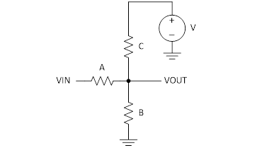
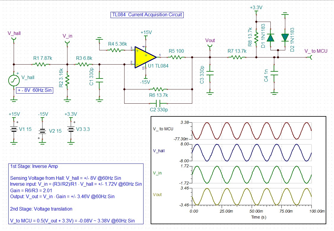
The +/- 8V (maximum range) sin signal @60Hz comes from the Hall sensor, then it is inputted to the inverting port of the amp through the divider network (R1, R2,R3). The gain is set at G=2. normally the output should vary around 0 level, thus +/- 3.46V (maximum range) sin signal @60Hz.
Finally, the +/- output signal will be translated to 0 ~ 3.3V signal, which is compatible with the MCU sampling port.
Now customer has 2 problems:
1. zero-input drift. when there has no current on the line, hall sensor has zero voltage and output should have zero voltage, but the output signal of the amp has voltage amplitude higher than 0.26V (threshold set by the MCU), triggering FAULT message.
2. Low temperature and high humidity working environment (condensate water around TL084): it still has no current on the line, hall sensor has zero voltage and output should have zero voltage, but the output signal of the amp has voltage amplitude @ 3.1V, triggering FAULT message.
These 2 problems are not easy to re-occur and customer are going to MP at the beginning of next month, could you help analysis?
Thank in advance and best regards,
Yang WU
TL084 current acquisition circuit.TSCTL084 Stability analysis.TSC
Hello Wang,
Before addressing this issue (in my next reply), I noticed that this circuit is far more complex than needed. The DC transfer function could be accomplished with just 3 resistors. Convert +/-8V to -0.08V to 3.38V
https://e2e.ti.com/blogs_/b/analogwire/archive/2016/09/20/three-ways-to-scale-an-analog-input-signal
In this case resistor A = 10k, B = 7621, C = 4325 ohms. V = 3.3V Round B and C to nearest 1% resistor or select a pair of 1% resistors that get closer to the desired value.
For example B=7621 could be 14k || 8060 and C=4325 could be 16.2k || 5.9k (5 resistor total)
Regards,Ronald MichallickLinear Applications
TI assumes no liability for applications assistance or customer product design. Customer is fully responsible for all design decisions and engineering with regard to its products, including decisions relating to application of TI products. By providing technical information, TI does not intend to offer or provide engineering services or advice concerning Customer's design. If Customer desires engineering services, the Customer should rely on its retained employees and consultants and/or procure engineering services from a licensed professional engineer (LPE).
In reply to Ron Michallick:
Hi Ron,
thanks for your explanation and solutions.
This circuit is inherited from the old air conditioner circuit and now used in the new commercial air conditioner project (though it's very complex...). The current acquisition is located at the 380V phase. the sampling frequency won't be high, supposing 1KHz is enough.
Considering customer cannot easily re-build this issue and MP urgency, it's difficult to identify the problem. As you said, I have been suggested customer to increase the phase margin.
thanks,
Yang