This thread has been locked.

If you have a related question, please click the "Ask a related question" button in the top right corner. The newly created question will be automatically linked to this question.

OPA170: OPA170 Charging Capacitor connected at non inverting input of I.C. under the influence of external Electromagnetic Field

Part Number: OPA170
Other Parts Discussed in Thread: OPA2990

Hello;

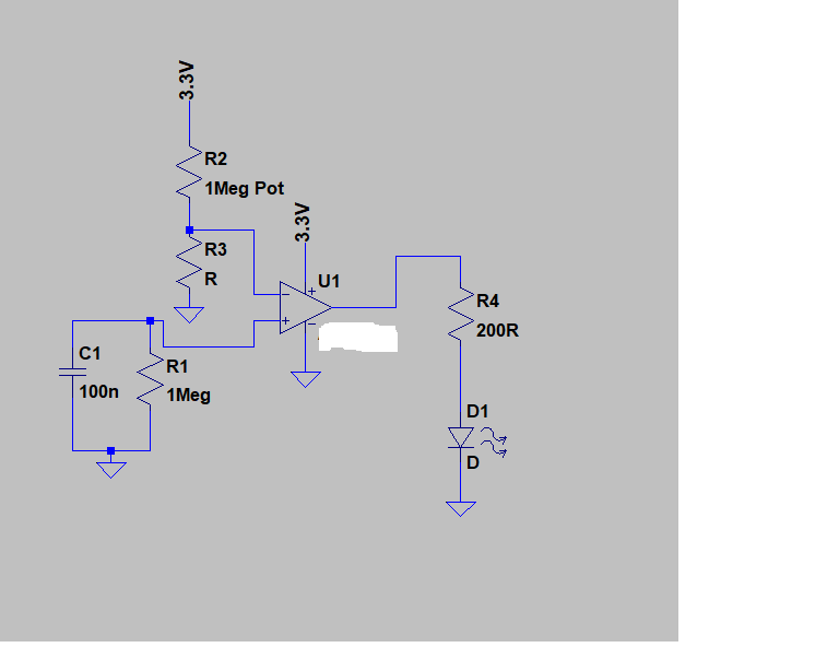
        We are using OPA170 as open loop  comparator where at inverting terminal is a  Pot to set reference threshold. At non inverting terminal there is a output of our circuit. Effectively at the i non inverting terminal of ap-amp is 0.1uF cap in parallel with 1Meg Resistor. 

          During normal operation there is no issue. But when this circuit is exposed to High electromagnetic filed then what we see is that 0.1uF gets charged to 0.6V TO 1V.  We initially through that EM waves might be inducing this voltage inside the circuit through a track or a loop But that was not the case. Hence finally what we did was keeping every thing same we just disconnected the supply pins of op-amp and tested again. This time there was no voltage observed across 0.1uF cap. 

             Hence want to know is it possible that due to external EM wave there might be high noise of power supply time and hence hence power supply is noisy at the supply pins of op-amp. Due to this noise on power supply will lead to strange behavior of the op-amp and hence it might be charging the 0.1uF capacitors which is at the non inverting input terminal of op-amp.

  • Hi Amey,

    the circuit sounds a bit strange to me. Can you show us a schematic?

    A 100n cap from the +input of OPA170 to GND? But this would mean, that the driving output sees a huge capacitive load. What drives the +input of OPA170? And why not providing a hysteresis?

    And what do you mean by "high electromagnetic field"? What is it?

    Kai
  • Thanks for quick response. Yet this is not a typical circuit where Op-amp is used as comparator. Please find the schematic below: Input+ is driven by a source which can drive huge capacitive load such as battery. what we observe is that if I keep circuit as shown below ( source driving C1 and R1 is  physically disconnected. Circuit is same as below) and when this is subjected to a high electromagnetic field then C1 is charged upto 0.6V-1V. there is no other source to charge up the capacitor except Opamp input or induced voltage due to EM wave. But when I remove 3.3V from the supply of op-amp and again subject the circuit to EM  wave then no voltage across C1 is observed that is op-amp is powered off and when EM wave is incident to this circuit then I dont get any voltage on C1. 

    Regarding EM wave It is field generated across wire which carries EFT as per IEC61000-4-4. 

  • Hi Amey,

    if a signal is given to the input of a OPAmp which is much faster than the OPAmp can handle, it can be observed sometimes that the input signal becomes demodulated and a pseudo input offset voltage can develop. Even the output of an OPAmp can behave this way. Internal ESD cells or unlinearity of internal circuitry can cause this demodulation. The best cure against unwanted demodulation effects is to provide sufficient input filtering.

    Additionally to this you should provide a hysteresis. This could also protect the input of OPA170 against overvoltages.

    Kai
  • Hi Amey,

    Kai is correct that the op amp will have an increase in offset voltage due to the EMI signal. I recommend reading EMI Rejection Ratio of Operational Amplifiers for an explanation on what EMIRR is and how EMI affect op amps.

    Additionally, the OPA170 is not recommended to be used as a comparator because the device has internal back to back diodes. When a differential input voltage is applied to the device the diodes will conduct and current will flow through the diodes. We recommend limiting the current to less than 10mA to prevent damaging the device (See the absolute maximum specifications table). However, the diodes are not designed or intended to be repeatedly turned on, they are only there to protect the device. I recommend using the OPA2990 which does not have internal back to back diodes.

    Thank you,

    Tim Claycomb