This thread has been locked.

If you have a related question, please click the "Ask a related question" button in the top right corner. The newly created question will be automatically linked to this question.

INA301: Transformer interferes INA301

Part Number: INA301
Other Parts Discussed in Thread: LM2903, INA300, INA381

Hi,

Below is the schematic. Actually, my customer used 3 INA301 with the same circuit, but only one had problem.Just 1A load will cause Alert. the designed over current is 13A, Rlimit is 25K. the shunt res is 7.5mΩ。 

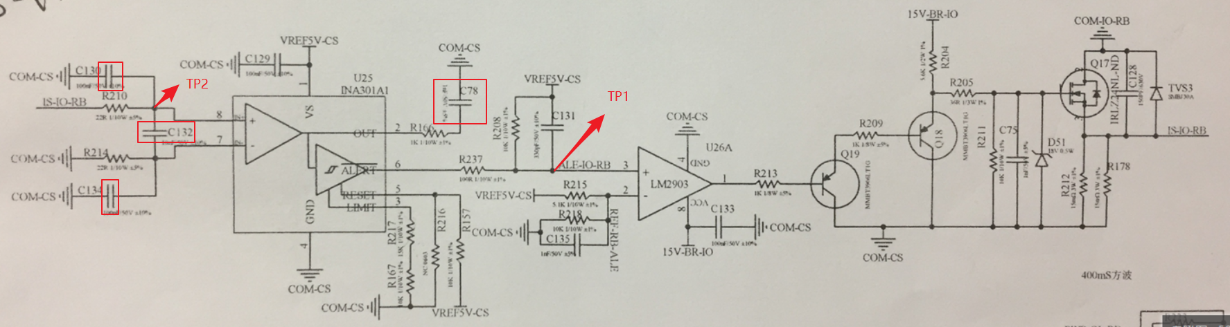
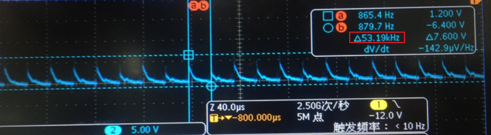
From TP1, can observe below waveform through  an oscilloscope

From TP2 ,the waveform is as below;

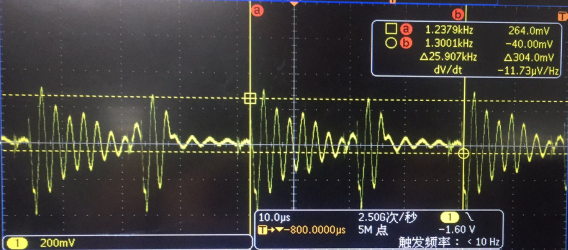
Apparently there was a wing at IN+. and tried to remove the capacitance marked with red box in schematic, the problem has not been solved..

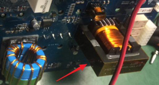
Then found  there is a big transformer on the back of the INA301 with problem. and the switch frequency is close to the number in the picture 2[57Khz]

. [below is the transformer, just right behind the INA301], and this is a two-layer PCB design.

My questions are:

(1) any suggestion to the root cause

(2)How to fix this?

(3)Any better device for this case?

Thanks.

  • Hi Yue,

    can you show scope plots of one of the proper channels for comparison?

    Is the INA301's internal comparator erroneously triggering? Or is only the signal TP1 wrong? If so, why not mounting a filter cap from TP1 to signal ground? And remove C131.

    If all this fails and if removing the transformer or adding a shield does not work either, I think I would enhance the low pass signal filtering at input of INA301.

    Kai

  • Hey Yue,
    1. How is TP1 measured? I’m guessing probe is referenced to the 5V rail because the “B” cursor says waveform is at -6.4V and this voltage would break the INA301 ALERT pin. Either ways the delta of TP1 is 7V and this greater than the VS supply and thus technically beyond the INA301’s Absolute Maximum Voltage rating for Alert pin. This leads me to believe that the probe itself it picking up some additional noise as well and that not all of the noise is really seen by LM2903.

    Overall, I do not think the INA301 is actually tripping to the 1A of current flow. I think this because if the INA301 was tripping, then it would hold the ALERT pin low indefinitely (forever) until device reset. This is because INA301 is in LATCH mode (RESET pin = HIGH). Thus, if INA301 is not tripping, then root cause is probably the transformer noise coupling to TP1 causing the TP1 node voltage drop from 5V to the LM2903 threshold voltage (3.31V?). Since INA301 is not cause of false trip here, I cannot recommend another device.

    Additionally, the TP2 waveform does not tell me anything about INA301 potentially being the issue. It shows the common-mode voltage of INA301 inputs and most likely the IN- pin has the same waveform and is offset by 1A*7m5mΩ.

    I think customer needs to focus on stabilizing the TP1 voltage. This could mean shielding all of the traces and components with a metal cover, or maybe removing C131 since transformer could be coupling to C131.
    Best,
    Peter
  • Ok. I will get back to you for the proper channel waveform
    BTW, Yes, it alerted only with 1A load. so I think the big problem is at the input side. can you be more specific about how to enhance the low pass signal fitering? based on my understanding, they do added the low pass filter network at the input. thanks.
  • Thanks for the reply. I got something . please wait for my further feedback.
  • Hey Yue,

    There is already input filtering set up for INA301. The most important enhancement should be increasing C132's. This is because the input differential voltage in between IN+ and IN- is what cause the INA301 to trip, not the common-mode voltage (VCM) which is TP2 because TP2 is measured with respect to GND. Actually, customer may want to try removing the common-mode caps (C130 and C134). If these capacitors are coupling to transformer noise then they could be charging and discharging at different rates, which would cause imbalance in the input differential voltage sense by INA301.

    Aside from all of this customer needs to verify that the INA301 is actually tripping at 1A. Right now it is not clear what system state is during the TP2 waveform or how the probes are connected.

    -Peter
  • Peter,   

    Thanks for the reply.   Would you please  help to suggest a P2P device first?   They used to use INA300, almost the same layout, no issue found, just the response is a bit slow, so they change to INA301.  

  • Yue,

    The INA381 is a similar part to INA301, but it is not the same pin out even though it is in 8-pin WSON. I'm confused the INA300 and INA301 are not P2P, so there must be different boards and layout used for each device. Maybe this layout has something to do with difference in noise coupling?

    Here are the analog-output current sense amplifiers that come in either WSON or VSSOP packages. Filter for only single channel devices.
    www.ti.com/.../products.html

    Even though these options are not drop-in replacements, they could serve same functionality.

    Another possible debug step for the engineer: remove the R and C from INA301 OUT pin. It does not seem like the design needs to read the voltage output of the device since INA300 was an original option.

    Best,
    Peter
  • Hi Yue,

    I would try to add ferrite beads in series to the both 22R resistors.

    Kai
  • Thanks for the reply. I will close this thread first.
    below is the summary, but no data support ,just discussed on the phone due to their engineer is not convenient in this week.
    (1) INA- also can observe the same waveform,just as you said.
    (2)they removed the R237 to cut off the connection between INA301 and LM2903, but still can observe the same output from INA301
    (3)LATCH mode for sure, they can only use this mode.
    (4)Tried the Q1 version, but problem is still there.
  • Kai,
    Also thanks for all your suggestions.