This thread has been locked.

If you have a related question, please click the "Ask a related question" button in the top right corner. The newly created question will be automatically linked to this question.

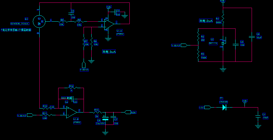
LPV802: Electrochemical gas sensor RS electromagnetic interference

Part Number: LPV802

Electrochemical gas sensor using LPV802 amplifier is easy easily disturbed by electromagnetic interference or Walkie-talkie (10V/m, 80MHz~1GHz). How to solve this problem?

Give me some advice,Thanks.
  • Greetings,

    Is the problem you are having similar as the pic below? This happens when I touch the body of the enclosure.

    I follow the same design recommended by TI's datasheet and sensor doesn't seem to be stable at all.

    Plus I have this lag when I stop exposing the sensor to gas. 

    Any insight would be much appreciated. 

  • Hi Denis,

    Can you provide some oscilloscope captures, to show in what way EMI is affecting your system?

    Best Regards,
    Bala Ravi
  • Hello Deniszmm,

    I assume you saw the following appnote on EMI testing on the LPV802:

    Comparing EMI Performance of LPV802 with Other Devices in a Gas Sensor App

    The small value (10-33pF) capacitors provide a direct AC path to ground for the induced RF. These should be as small as possible to minimize the inductance (0402 or smaller - 0201 is best)

    How the circuit responds to EMI is completely layout dependent. If you want to pass these EMI tests, you need to lay out the board as if it is an RF board;  Solid ground planes, multiple ground vias, short traces, ferrite beads, small value caps at all the I/O points. All the tricks used for keeping a PCB from radiating RF also helps preventing/reducing EMI susceptibility.

    It is extremely difficult to make the design "EMI Proof", but you can try to make it as EMI resistant as possible. There comes a point where you cannot do much more without serious changes to the circuit performance. Armored trucks and tanks can't move fast for a reason...

    A walkie-talkie against the board is a severe test - exceeding 100V/meter equivalent. In the field, there should be some shielding (and distance)  between the radio and the board.

    The sensor itself may also be affected by the RF. There is little that can be done on the amplifier side if the sensor reacts to the RF. The sensor may need to have a RF screen enclosing the sensor.

    As to Anil's point - You did not say what type of sensor you are using, but gas sensors can get saturated when exposed to high concentrations for extended times. This can cause shifts in the zero baseline, maximum output and recovery time. They should be given a "break" every so often in fresh air.

    How fast the sensor responds is dependent on the sensor types, size, construction, gas flow and enclosure, and if they have any internal filters that may need to purge/out-gas. The response time should be indicated on the sensors datasheet. The cal gas should be immediately followed by "clean" gas. Also, do tests in a well ventilated room if the gas is not purged, otherwise the gas background concentration can increase causing a zero baseline shift.

    Also - R13 needs to be much higher than 2k - you are almost guaranteed an oscillation. Change R13 to 20k and remove C6.

  • Hi Deniszmm,

    the best cure against EMI is to put the whole circuit together with the gas sensor inside a Faraday cage. Connect the Faraday cage to signal ground. Make an opening in the Faraday cage above the gas sensor and "seal" the opening with a metal mesh to allow the measuring gas to enter the gas sensor. Don't forget to make a conductive connection between the metal mesh and the Faraday cage.

    Kai
  • Thank you for your advice!

  • Thank you for your advice.I will further optimize the circuit according to your Suggestions