This thread has been locked.

If you have a related question, please click the "Ask a related question" button in the top right corner. The newly created question will be automatically linked to this question.

LM2907-N: Component selection help needed for RPM to voltage converter

Part Number: LM2907-N
Other Parts Discussed in Thread: LM2917-N

I am trying to get clarification on a couple different aspects of the device. I am planning on powering the device with a 5V source and the RPM signal will switch between 0V-5V with a maximum frequency of 835Hz (100RPM = 3.325Hz)

I would like to get confirmation if my component selection is correct, or if I should reevaluate my component values.

R1=100k

C1=12nF

Based on the values of R1 and C1, I calculate that I will be getting approximately 167Hz/V resolution. Are my calculations correct?

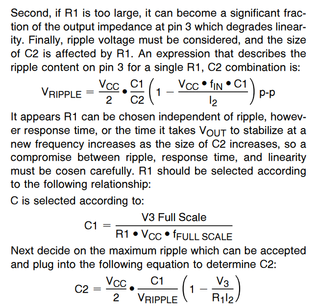
Second question is in regards to the response timing associated with selecting C2. I want to be able to measure the frequency with +/-100RPM accuracy (+/-3.3Hz). Based on that, I have a maximum tolerance for a 20mV-ripple. What kind of response time can I expect based on the max Vripple requirement that I have? The equations on the application note don't clearly state how to calculate the I2 value for any of the following equations.

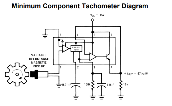
There was no clear indication at to how much of a response time delay will be present in the minimum circuit shown on the datasheet.

It was also unclear if I could use a 0-5V RPM signal with a Vcc of 12V. Would that help reduce my Vripple?

  • Hello Furqan,

    The LM2907-N is usable with supply voltages of 6 V to 24 V so a Vcc of 12 V is good. The LM2907-N when powered by a single, positive supply must have an input that crosses below 0 V by a small negative amount to activate the input comparator. You can see from the above application diagram that the pin 8 comparator input is connected to ground and that is why the input signal applied to pin 1 must pass through 0 V and go slightly negative. Therefore, a true 0 to 5 V input will not trigger the comparator. The variable reluctance magnetic pick up produces a waveform where a portion of the waveform goes below 0 V for a portion of the time. Alternately, a series input capacitor can be added at pin 1 which forms a differentiator with an LM2907-N internal input resistance to ground. That will result in input pulses that have a period when the voltage drops below 0 V.

    I am planning on powering the device with a 5V source and the RPM signal will switch between 0V-5V with a maximum frequency of 835Hz (100RPM = 3.325Hz). I would like to get confirmation if my component selection is correct, or if I should reevaluate my component values.

    R1=100k, C1=12nF - Based on the values of R1 and C1, I calculate that I will be getting approximately 167Hz/V resolution. Are my calculations correct?

    Based on a Vcc = 12 V and output voltage of 12 V the R1 and C1 values would be correct. But realistically, the LM2907-N output won't be able to pull all the way up to 12 V and maintain good linearity. A more realistic expectation is that the output will be able to achieve a 10 V output, with Vcc = 12 V. In that case R1 = 100 k and C1 = 10 nF. For a 0 to 5 V input range the input resolution would be 167 Hz/V as you have stated.

    I want to be able to measure the frequency with +/-100RPM accuracy (+/-3.3Hz). Based on that, I have a maximum tolerance for a 20mV-ripple. What kind of response time can I expect based on the max Vripple requirement that I have? The equations on the application note don't clearly state how to calculate the I2 value for any of the following equations.

    The datasheet doesn't say much about I2. It appears that it is the tachometer output current listed in Table 7.5 Electrical Characteristics as:

    I2 , I3 Output current    Test Condition V2 = V3 = 6 V (see note 3)     Min 140 μA   Typ 180 μA   Max  240 μA

    Try applying the typical value in the equations to arrive at a C3 value that meets your maximum ripple value.

    The datasheet and application notes almost no information about recovery times. About the only hint and it is for the LM2917-N with a particular condition where R1 = 100 k, C1 = 10 nF, and C2 = 1 uF is shown in 10.2.1.3 Application Curves, Figure 16. Output Response to an Increase in Input Frequency. In that case, changing the input frequency from 68 Hz to 136 Hz, required about 250 ms to achieve the new output level.

    It stands to reason that as C2 is increased in value the ripple will be reduce, but the time required to settle increases.

    Regards, Thomas

    Precision Amplifiers Applications Engineering