This thread has been locked.

If you have a related question, please click the "Ask a related question" button in the top right corner. The newly created question will be automatically linked to this question.

TL084: TL084 latch up information

Part Number: TL084
Other Parts Discussed in Thread: LM324

Hi sir,

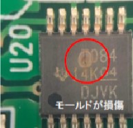
Please I greatly appreciate if possible to have information on latch up data for TL084.

Our equipment delivered to our cusomer had a trouble and returned to us. Two chips of TL084 were burned out and looks due to latch up.

regards,

hideki

  • Hello Hideki,

    Please provide the full part number and the date code on top of device (if still readable). What is the power supply voltage for the op amp?  

    Latch up generally occurs when pin voltage exceeds the supply voltages. Does that happen in this application?

  • Dear Mr. Michallick,

      Thank you very much for your quick response.

    The parts number is TL084CPW and we use it with 24V/0V in our equipment.

    We are trying to reproduce this happening in our lab like aplying exceeded voltage but nevere happend so far.

    But please note our customer hit this same troubles twice for two equipments. ( it means totaly four times)

    I greatly appreciate your any sugestions.

    best regards,

    hideki yamada

  • Yamada,

    While I look into the date code history, can you clarify "same troubles twice for two equipments. ( it means totals four times)".  Does that means on two different boards, two devices on each board were damaged like this? This would mean something in common with both locations is part of the cause. Do the four device share the same date code or different ones? The picture is "14KDJVK"

    Do any pins on the TL084 go to any board connectors or are connected directly to ground?

    Basically any and all clues will be useful to determine a cause any improvements that can be made.

  • Hi Mr. Michallick,

      Your understanding is correct. We shipped more than two equipments to customer and two equipments were failed due to this trouble. One equipment has two TL084CPW on one borard. Four TL084CPW have same sate code "14KDJVK". 

     Two LM324 ware connected to the common VCC+ and VCC- on the same board but they are not damaged. VCC+ and VCC- are connected to VDD and GND direction and other pins are conneccted to other deviceds.

    Additional information is that we could succeed to reproduce this failure by IEC 61000-4-4 Electrical fast transient/burst immunity test. When we applied this test the equipments, same troubles were happend and it was repeated.The date code are 74K00XN and 74KCOXN.

    I greatly appreciate your continueous support.

    best regards,

    hideki yamada

  • Hello Yamada,

    The Electrical fast transient/burst immunity test results are interesting. Was this test applied just to the system power or also to other entry points in the system? Is this the first time testing with EFT or did a previous qualification (done in the same) have a passing result?

    Quality test looked up date code and no anomalies were found. The results on the more recent material suggest that samples used is not important. 

  • Hi Mr. Michallick,

      We applied this test on only power line (VCC/GND). This is the first time to take this test and the equipment passed this test at level 2 (1kV for power line) but failed at level 3(2kV). I applied this test to two equipments and they are same result. The current our conclusion is TL084 were latched up because of power line noise so that I would like to have TI's TL084 latch up test report especially for VCC+ and VCC- pins.

    As I mentioned, there are two TL084 chips on the same board and both chips were failed. From I-V curve analysis, one chip's VCC- was cut off and another chip's VCC+ has high impedance between VCC+ and INPUT/OUTPUT pins (5-6MOhm).

    best regards,

    hideki yamada

  • Hi Hideki,

    burst is a common mode interence referenced to protection earth. It enters your system and searches for a path back to protection earth. This often causes the burst currents finally running over the signal ground routing of your circuit.

    The best cure against burst is to use a solid ground plane to provide the burst currents a low ohmic and low inductive path across your signal ground.

    If signal lines travel over the whole board or come from outer world you should think about filtering (low pass filter with a C) and/or protecting (TVS + current limiting resistor) the inputs, outputs and supply pins of TL084.

    A burst damage is nearly always an indication for an improper filtering/protection and the lack of a solid ground plane. So, it could have damaged the LM324 as well...

    Kai

  • Yamada,

    I do not have EFT test equipment in my lab. Do you know how high the voltage (VCC-GND) becomes during the 2kV test?  I can run pulse testing to see if that has the same result. Going forward do you want to consider a replacement part number that has a higher tolerance?  

  • Hi Kai,

     Thank you for this worthy advice. The reason why we applied "Electrical fast transient/burst immunity test" was to reproduce the latch up of TL084 which might be happended at our customer site.

    We got the power supply system from customer yesterday and we found very noisy power supply into the equipment. Now I could understood the root cause of this trouble.

    Our current focus is to remove the noise from power line.

    Thak you again your help.

    best regards,

    hideki yamada

  • Hi Hideki,

    I think you just destroyed the TL084 by overvoltage at the supply pins during the burst test.

    Are you sure that your burst measurement setup is correct? As I already said, the burst test is a common mode interference test. You must not apply the burst voltage directly between VCC and GND!

    2860.4_Transient_immunity_testing.pdf

    I think your customer's power supply is the issue. As you said, it's very noisy. So, it's very probable that it emits overvoltage spikes that can destroy the TL084. This need not necessarily have to do with the occurence of bursts. I would use a different power supply.

    Kai

  • Hi Kai,

    I absolutely agree with you. The intention to use the burst test was to reproduce TL084 failure happened at customer's site since we assumed customer's power supply destroyed TL084 by latch up.

    We got customer's power supply system and found out the noisy power line but still TL084 is not failed today at our lab. We are going to apply the burst test with customer's power supply system as the additional noise to see the margin.

     The current our focus is to improve power supply in order to avoid noisy power destroys TL084.

     Thank you again your advice!


     hideki yamada

  • Hi Hideki,

    improving the power supply is a very good idea. An OPAmp always needs a clean, stable and noisefree supply voltage with a low source resistance. If the power supply does not fullfill these requirements, it can be tried to use an RC-filter in the supply line of each OPAmp. In audio circutis I often use 100R and 100µF//100nF. But the actual values depend on your circuit and application, of course. An alternative could be the use of a linear post-regulator between the power supply and the OPAmp circuit. I think of the LM78xx or a LDO.

    Kai

  • Kai,


      Finally we found out the circuit protector between power supply and equipment caused this issue.

    The circuit protector has an electromagnet inside on the power line to switch off for over current incident.

    This electromagnet has inductance of 150uH at 1kHz so that it looks it amplifies the noise at equipment side.

    When this circuit protector was bypassed, the power noise was disappeared and very stable.


      We are considering to modify the power panel to get more stable power supply and I will include your advice for the power supply for next design.


    Thank a lot for your worthy advice.


    best regards,

    Hideki yamada