This thread has been locked.

If you have a related question, please click the "Ask a related question" button in the top right corner. The newly created question will be automatically linked to this question.

OPA847: Not work for Instrument amplifier

Part Number: OPA847
Other Parts Discussed in Thread: OPA838, OPA835

Hi,

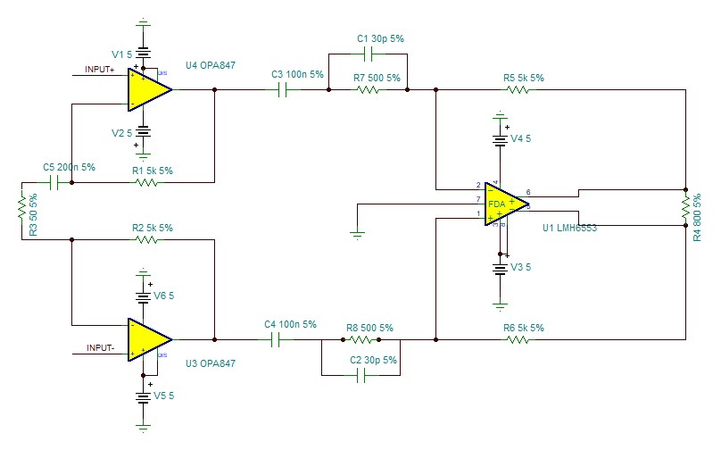
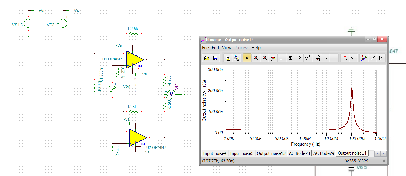
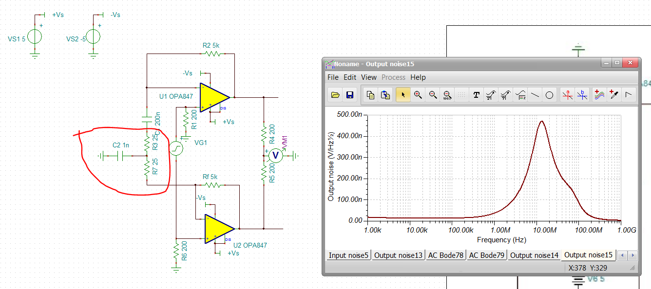
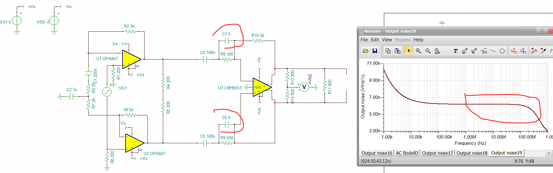
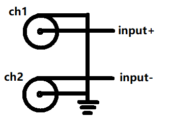
The following is my circuit. 

It work well when simulating But not work After I solder this circuit on PCB.

I want to know if opa847 don't use the Non-inverting Input in differential and it just only use the inverting input like in datasheet(page 1).

Anyone help me, thanks!

  • Hello Bohai, 

    It is possible you have a common mode oscillation in that first stage, Split R3 into two 25ohm values and put a 0.1uF cap to ground in the middle, This will peak the output CM noise quite a lot - but, the FDA will reject all that. 

    We ran into this on the OPA838 as well, check out section 9.1.5 in the OPA838 datasheet, 

  • Also, why are you using 5% R's in the FDA ckt. That will give you quite a lot of gain imbalance which becomes CM to DM conversion. In some other work lately we have found even 0.1% R's are quite inexpensive in volume these days - that would help your performance over production spread a lot. 

    You might try a worst case gain imbalance and drive a CM signal into the FDA stage and see what I am talking about in sim. 

  • Hi Michael,

     I have see the opa835 datasheet (9.1.5). I know this problem.Next week,I will test it.  Thank you for your help.

    Also,I want to simulate  the common mode oscillation. I don't know how to do it. Could you give me any document about it.

    Thanks

    Bohai

  • Hi Michael ,

    This is my missing. I use the Tina default precision. I forget to modify it.  In fact, I use %1 R‘s in this.

    Thanks

  • Hello Bohai,

    The easiest way to see this to look at the output CM noise, as shown here and in the attached file, 

    Diff OPA847 CM Noise test.TSC

  • And then splitting that Rg into 2-25ohm with a 1nF to ground gives a lot of CM noise peaking, but you can tell by how broad it is this is just gain peaking not resonance - the FDA will reject this, pretty cool actually, 

  • And adding the FDA stage we see another issue at higher F looking at the final output CM noise - I was expecting to see this pretty low, rejecting the peaking out of the diff OPA847 stages. not so, nasty resonance at 400MHz, 

    You need to remove those 30pF, not doing anything for your diff signal path and causing this issue, now this is what I expected, complete rejection of the CM noise coming into the FDA stage, 

    Diff OPA847 CM Noise test with FDA.TSC

  • Hi Michael,

    I modified the circuit according to your advice.And I test it. I found the circuit is still abnormal. 

    So,the noise gain peaking don't lead to the abnormal. Maybe some reason lead to it.

    I don't know if the PCB layout lead to it. I plan to re-layout the PCB and test it.

    Thanks

    Bohai

  • Well there are always other things that could also be going on - 

    1. When you probe on the circuit, do not probe directly but through a 100ohm isolating R to avoid putting Cload on the I/O pins

    2. You do have a lot of gain, make sure your power supplies are not providing a path of oscillation - use ferrite beads and 10uF in parallel with 100nF at the supply pins 

  • Hi Michael,

    I have solved this problem.

    There are two problems about this:

    1.Probe directly on the circuit

    2.My input signal is single-ended signal not differential signal.

    Not work for single-ended signal input:  

    Work for differential:

    In fact, all is my test method lead to this problem.

    I am so sorry for my pool English. 

    In the end, Thanks for your help!