This thread has been locked.

If you have a related question, please click the "Ask a related question" button in the top right corner. The newly created question will be automatically linked to this question.

TL071: Will this circuit oscillate?

Part Number: TL071

Hi!

I have redesigned my transistor tester but while this project right now just is paper project I wish for someone to tell me if it is worth building or not.

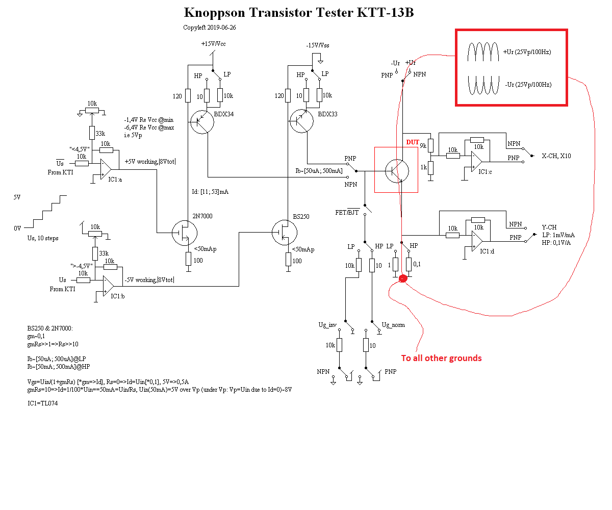
One thing I like is that a non-filtered rectified transformer voltage constitutes Ur which means that high output currents and/or voltage is easy to achieve without complications such as OP oscillations.

Best regards, Roger

  • Roger,

    Most things are forward following, opposed to feedback loops. That promotes fast acting and stable operation.

    Add a resistor spot between IC1 and FET gates. Should work fine at zero ohms, but better safe than sorry.   

    The highest current loop is the 'Ur' loop , so connect this ground to all the other grounds from a single point per drawing.

  • Hi Ronald!

    Thank you very much for your tip!

    I will do as you so kindly say, especially that part with a "gate-stopper"-resistor, that technique has been used for a long time with regards to tubes, I have however never understood why :)

    I will also carefully consider the "Ur-tip" regarding "star" grounding.

    Finally, I like the "unlimited" power you can supply to the KTT by simple use of an unfiltered rectified transformer (remember, this is not my idea, I have just stolen it :) ).

    Best regards, Roger

  • Hi folks!

    Just want to show you the stimuli for my revised transitor tester.

    I seem to be able to use my original stimuli (KTI-13A) with just a few changes, I have noted these changes in the Eagle schematic below.

    Remember that many of the components now are useless but I now have both Us and an inverted Us.

    Us is syncronized with the non-filtered supply used for Ur generation.

    Best regards, Roger