This thread has been locked.

If you have a related question, please click the "Ask a related question" button in the top right corner. The newly created question will be automatically linked to this question.

Gas sensor circuit in application information

Part Number: LPV802

Hi there

In LPV802 datasheet

http://www.ti.com/lit/ds/symlink/lpv802.pdf

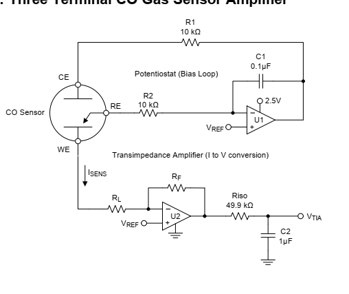
Page-14 has an application circuit information. It shows a potentiostat circuit. & transimpedance amplifier.

This is one of the very few application notes that I have found that has information on this type of circuitry. So, very helpful (thank you very much for sharing this information)

My question is about the component calculation / selection for the resistors & capacitors around potentiostatic circuit (Not the transimpedance amplifier)

The resistors R1, R2 & Cap C1

The datasheet says R1 is to maintain stability due to the large capacitance of the sensor. C1 and R2 form the Potentiostat integrator and set the feedback time constant.

I am trying to figure out a method to calculate these component values OR how the designer came up with the values of

R1 = 10K

R2 = 10K

& C1 = 0.1uF

Although gas sensor manufacturers don't provide the capacitance value for the sensor but roughly say anything from 1mF to 3mF (based on some notes from Alphasense)

So, if we had a sensor of say 1mF and want to use same LPV802 amplifier then how would one calculate these R1, R2 & C1 values (even though the sensor would most likely work if I just use this circuitry), but I would like to understand the underlying methodology to calculate these values!?

  • You might take a look at this app note, but basically, the R1 C1 set the integrator time constant to servo the CE voltage to Vref - R1 is like Riso, isolating the op amp output from an unknown large C - both seem unnecessarily high valued here if you consider their noise.

    http://www.ti.com/lit/an/snoa514c/snoa514c.pdf

  • Michael

    Thank you for the feedback.

    Ok understood that R1 is like Riso to isolate Sensor's capacitance from the Opamps's output to avoid instability.

    But I am still confused about the R2 & C1 (integrator circuit). How is it actually relevant here and how is it effecting the performance of the circuit.

    If I were to simulate this circuit to test its functionality. I could close the loop by shorting the CE & RE points & then measure the voltage at RE pin to see if it is same as set as VREF (non inverting input of U1).

    What test signal I could use to check the functionality of this R2/C1 integrator and perhaps understand the function of it here.

  • Hi NS,

    The purpose of the integrator is to keep RE (reference electrode) at the same potential as Vref. Yes, you can simulate this circuit by shorting CE and RE and measuring the potential at RE (this should be equal to Vref). 

    You can choose the values of R2 and C1 based on your bandwidth and time delay of interest, because they also act as a filter to the input of the op-amp. 

    Best Regards,

    Bala Ravi

  • NS,

    These sensors are very noisy, and slow (seconds)

    The large integration cap and output filter are to provide simple analog filtering and averaging.

    As opposed to "digital" averaging that takes several ADC cycles and processing for each sample period.

    mainly...the cap values were chosen because they were in the drawer....No magical formulas..

    R1 does isolate the capacitance from the output, but the sensor also has fairly high impedance on the "other" side of the sensor, so the total impedance the amp sees is pretty high. So you don't need the full 50k isolation.

    The circuit in the datasheet is a subset from this TI Design and goes into more detail:

     Micropower Electrochemical Gas Sensor Amplifier Reference Design

    As noted in the above document, there is a upper limit to the value of R1, as this is the current path for the sensor and if it is too large, there will be too much voltage drop and the amp output rails. So you should size R1  with the maximum sensor current in mind and the allowable voltage drop.