This thread has been locked.

If you have a related question, please click the "Ask a related question" button in the top right corner. The newly created question will be automatically linked to this question.

OPA211: Using OPA211 as VCOM driver with LME49724.

Part Number: OPA211
Other Parts Discussed in Thread: LME49724, , OPA1632, THS4551, OPA1692, THS4131

Hello,

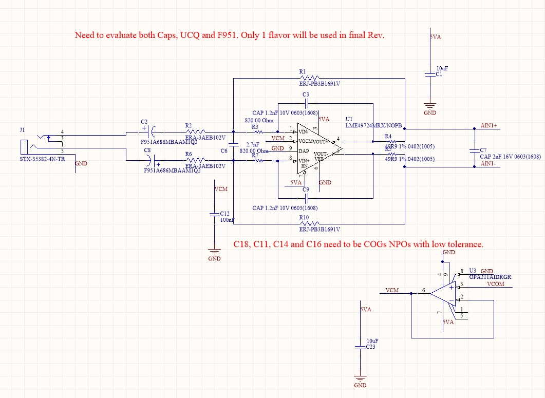
I am using OPA211 in unity gain as a Vcom pin driver to LME49724. The output of the LME49724 is driving my ADC in a MFB configuration.

I would like to know how large of a cap i can put on the output of OPA211 to filter out any excess noise and still have OPA211 be stable.

Since this is a DC application for the OPA211, does it matter if I exceed 1 nF at the output... I saw on the datasheet that you would get 40% overshoot with 200 pF at unity gain.

Thank you so much.

  • Hello Taoufiq,

    Well a lot here - but lets start

    1. The LME49724 is a great audio FDA, If you need that high supply operation,a good alternate is the OPA1632

    2. If you really only need to support a <=5V ADC, and can use a 5V FDA, the THS4551 has the lowest HD in the audio band of any part

    3. The cap on the Vocm pin only helps Vocm output noise - that can only get into a differential noise through feedback element mismatches. usually not a big issue, but if you must put a cap there, make sure you add the necessary Riso from the OPA211 output for its stability

    4. MFB filters are a big interest for me and I have developed a number of advanced design tools, if you told me your target specs and minimum input resistor you want to drive, I could ship a design pretty quickly. Best to settle which FDA first as the design flow accounts for a number of device parameters (like parasitic input differential C). 

  • Michael,

    Thank you so much for getting back to me. I ordered samples of the OPA1632 that way I can AB against the LME49724. I will be running this on 5.4V and need a 2V rms THD that can be as low as possible.

    I noticed that OPA1632 does not have 5V THD characterization charts, but LME 49724 does, so it was easy to get a THD at 5V for the LME49724.

    Anyhow, I will keep the Riso in mind if I put anything higher than 1 nF on the OPA211. Let me share what I put together on the MFB section with you, and please do tell if you can see any improvements.

    The ADC is oversampling at 6 MHz, and my Audio bandwidth is 50 KHz (We make 50 KHz Mics). Phase linearity and minimum passband magnitude ripple are of utmost importance to me. The good news is the OPA1631 comes in an SOIC8 so I will be able to drop it into the board I have now and do a comparison with the LME.

    Any ideas are welcome and thank you so much for the awesome support.

  • Hello Toufiq

    No, I had not actually seen that you had replied, Few things here 

    1. Yes, I see the LME49724 reports what looks like -120dBc in  a plot 

    2. But, if you work backwards on the output swing with +/-15V supplies, that solves to a 2.5V headroom, which can't be right. 

    3. So, we made quite a few improvements to measure audio distortion in the more recent high speed parts. 

    4. 2Vrms is +/-1.41V around the Vcom on each output pin

    5. The RR out THS4551 could do this on a 5V supply with no problem, and if you check its <50kHz HD plots, <-135dBc. Much better on paper than these audio FDA's

    6. now, for the filter - I can't read all the R values, but I am sure I could suggest some improvements - This does look like an MFB - we would attach the feedback C outside the output R's, but you might be doing the Cload drive circuit here as some combination with the Filter? 

    7. If you are just DC centering the Vocm on the supply, most FDA's default to that with no external amp,just need a cap and no OPA211. 

  • Also Taoufiq, 

    On another recent filter discussion we were having, we discovered that 2% C0G caps in E24 values are relatively inexpensive these days. The last step in my MFB design flow is to snap to best fit E24 caps and E96 R's. I think we also found that 0.25% E96 R's were pretty cheap as well. The free TI TINA does not support monte carlo, but the V11 I bought does.

  • Looking more closely at the OPA1692 output swing, it specifies only a 0.2V headroom, 

    However, that is probably an error. This part was simply a remarketed (for audio) version of the THS4131. That part shows a 0.9V headroom, which makes more sense for this non-RR output device. 

    The THS4131 was also one of the parts we re-tested for HD with our new methods back in the early 2000's time frame, Did a lot of retesting of parts that had previously been limited by filter based approaches - that was the easy part, updating data sheets is not - so they were never updated, I will be discussing this approach in a 3part Audio Express article coming up later this year. So this plot applies to the OPA1692 also. 

  • Michael,

    Thank you for the replies. After studying all the datasheets, my best bet at TI is the THS4551. I ordered some samples for evaluation.

    I used the Prism Sound to generate my stimulus and ran the output of my ADC via USB to an audio software tool and was able to confirm that the LME49724's THD would start degrading rapidly

    around 0.85 Vrms (Aligns with the datasheet at 5 V). So it's clearly not going to cut it for me. It is however a great part for high headroom and has stellar noise performance. 

    As far as the MFB; RF= 1.691 K and RG= 1K. Those are both 0.1% from Panasonic. I use C7 2nF the output cap as both an extra high frequency pole for my filter to give me some extra attenuation before I hit (6MHz - 50 KHz = 5.95MHz) and also as a charge reservoir for my ADC. I'm trying to hit better than 100 dB attenuation at 5.95 MHz while maintaining great phase linearity and having minimum passband ripple.

    As usual, thank you for the amazing comments.  


  • Thanks Taoufiq, that was all I needed, 

    The THS4551 is a great part HD wise, I have run into phase margin problems with circuits like yours due to the reactive Zol in these RR output stages. Fortunately, unlike some other FDA suppliers, we have that in the  TINA model. 

    Here is a file where I stepped through your circuit (18deg phase margin) and a slight LG improved RC solution - that one oscillated for sure, but a couple of small changes pulled it up to 45deg phase margin (and those would improve your original design as well). 

    Some review on a THS4551 based audio MFB filter.docx

    Got into this same issue in this article, 

    https://www.planetanalog.com/author.asp?section_id=3404&doc_id=565122

  • was able to get the original RC values to run on SNR, here I added those phase margin improvements and get about 106dB SNR. little better than the modified RC solution at 104.8dB - it is that higher R inside the loop filter which is also why the NG peaking is lower. - you might not be able to open this first one, saved as V7 and inserted a 2nd time. 

    THS4551 audio MFB.TSC

    And this file, this was your original RC with those small changes to improve on the original 18deg phase margin when you go to the THS4551

    THS4551 audio MFB.TSC

    here is the sim snip

  • Morning Taoufiq

    I had made an error on the differential C value in my updated RC design, I also adjusted the design flow to reduce the value of the resistor inside the filter loop to increase SNR. So this solution is about the same SNR as your original values and still has the 2dB increase in the min LG, 

    Here is this sim file,

    The gain is slightly higher here, I solve for best Fo and Q fit and let the gain go off one standard E96 value if need be. 

    THS4551 audio MFB updated RC 2nd pass.TSC

  • And to continue, here is a monte carlo run with 0.1% R's and 1% Cs, not much to look at, real tight distribution

  • And, as I was shutting these TINA files to move on to something else, I updated the LG sim to the values in the prior posting, Shows 50deg phase margin. 

    If I connect the filter feedback caps to the FDA output pins (instead of outside those 20ohm inside the loop) it drops to 18deg. That is the reactive Zol interacting with the the feedback caps.

    Look at figure 68 in the THS4551 datasheet, that Zol is in the TINA model and is in fact real in the device. 

  • Michael,

    Thanks a lot for the awesome help. Much appreciated. I did look at the Zol peaking (becoming inductive) at high frequencies, which is interesting.

    Also, having the proper model of the THS4551 to be able to do accurate LG sims is very important for such a high bandwidth FDA. So thank you for that.

    I will ran a couple of final sims on that proposed design and hopefully I should be good to go.

    One last thing, i think I will bypass the VOCM with a 1 uF to minimize noise from that pin. 

    Thanks a lot Michael. 

  • You are welcome Taoufiq, 

    You always have to think self resonance on those noise filter caps, maybe 10nF would be better on the Vocm pin.