This thread has been locked.

If you have a related question, please click the "Ask a related question" button in the top right corner. The newly created question will be automatically linked to this question.

OPA541: Dammage of OPA541AP with inductive load when the output goes quickly from -Vs to +Vs

Part Number: OPA541

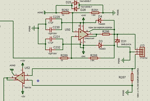
Here is the schematic of the driver. The input sense is destroyed when the output goes from -Vs to +Vs commuting 3A

We have 6 drivers fixed on the same heat sink. That means all the packages are connected electricaly together through the sink. Is it a problem ?

The temperature of the sink is 90°C, is -it a problem ?

  • Hello Gilbert,

    Sorry you are having problems with your OPA541 application. Driving an inductive load can be much more thermally challenging compared to a when a purely resistive load is being used. The OPA541 datasheet in the 8.1.3 Safe Operating Area section states, "Reactive or EMF-generating loads such as DC motors can present difficult SOA requirements. With a purely reactive load, output voltage and load current are 90° out of phase. Thus, peak output current occurs when the output voltage is zero and the voltage across the conducting transistor is equal to the full power supply voltage." It is difficult to know at this point if the failure is due to a thermal condition, or something else.

    You have established that the OPA541 input sense is being destroyed. Does that mean that the input circuits of the OPA541 are being damaged, or is this a broader term meaning the OPA541 used in the sense function is being damaged?

    There are two common causes for the failure of power Op amps; thermal induced failure of the output transistors, and electrical overstress (EOS) of one of the pin functions. We would need to know more about the load being used in the application, the input signal characteristics and more details about the output waveform as it slews from -Vs to +Vs. Does the damage occur to the OPA541 if the output slew is from +Vs to -Vs?

    You should be able to mount several OPA541 Op amps on the a common heatsink providing they are all operated in like conditions. I assume your OPA541 devices are in the 11-pin TO-220 KV package, in which case the package thermal tab is at an internal potential of -Vs. Therefore, if the TO-220 packages are not electrically insulated from the heatsink, the heatsink must be connected to the -Vs potential, not ground. Please check how you have the tabs connected to the heatsink.

    Regards, Thomas

    Precision Amplifiers Applications Engineering 

  • Hello Thomas,

    In fact if I send the signal to the OPA541, it has no reaction. the output gives always 0,009 A, that's why we thaught it's the input sense that have been destroyed but it's not sure.

    The damage occurs at a dirac response of the output of OPA541 from +Vs to -Vs (or -Vs to +Vs). If we make a pulse with a slope from +Vs to -Vs there is no damage.

    The charge is inductive 194µH 0,9ohms( with small capacitors for cables).

    Yes we are using 11-pin TO-220 KV package. The 6 thermal tabs are electrically connected to the heatsink but the heat sink is not connected to -Vs, it's connected to nothing.

    Have you an idea of a solution to prevent the damage (protective component) ?

    From my side : i will change the heatsink to decrease the temperature to 70° and use a slope instead of dirac pulse to make the commutation.

    Gilbert

  • Hello Gilbert,

    Thank you for the additional information. Here are my thoughts regarding your comments about your OPA541 application.

    In fact if I send the signal to the OPA541, it has no reaction. the output gives always 0,009 A, that's why we thaught it's the input sense that have been destroyed but it's not sure.

    • If I am interpreting this correctly you apply an input signal, but you see know output response other than it sources a continuous 0.009 A dc current. Can you tell me the details of input signal you are applying? A normally functioning OPA541 should amplify an input waveform that is within its operating bandwidth.

    The damage occurs at a dirac response of the output of OPA541 from +Vs to -Vs (or -Vs to +Vs). If we make a pulse with a slope from +Vs to -Vs there is no damage.

    • Does this mean that a dirac response such as a pulse having an amplitude of +Vs to -Vs is being applied to the output pin? If so, is the load you mention part of that circuit?

    The charge is inductive 194µH 0,9ohms( with small capacitors for cables).

    • You mention "charge." Is that load charged up in some manner and then applied to the OPA541 output pin?

    Yes we are using 11-pin TO-220 KV package. The 6 thermal tabs are electrically connected to the heatsink but the heat sink is not connected to -Vs, it's connected to nothing.

    • Okay, If the heat sink is floating and not connected to any external potential it should take on the bias voltage that is present on the OPA541 TO-220 mounting tab, -Vs. We usually hard wire the heat-sink to -Vs, but as long as it is floating I believe the OPA541 devices will be okay.

    Have you an idea of a solution to prevent the damage (protective component) ?

    • The OPA541 is one of our legacy power Op amps and the protection methods mentioned in the datasheet are not our most modern recommendations. The 1N4003 diodes connected from the OPA541 output pin to the supply rails isn't what we recommend today. They would be replaced with higher current, very fast recovery silicon rectifier diodes. These would be in place to conduct any current produced by the back EMF of an inductive load. Then, high power transient voltage suppresser (TVS) diodes are added from the Vs+ and Vs- pins to ground. They provide a return current path to ground for any current associated with a back EMF event. The power supply bypass capacitors play a role as well during a transient event. Here is an image of the protection plan.

    Please note that I will be on international travel to Asia starting Friday and my ability to assist with e2e inquiries will be limited at best.

    Regards, Thomas

    Precision Amplifiers Applications Engineering