This thread has been locked.

If you have a related question, please click the "Ask a related question" button in the top right corner. The newly created question will be automatically linked to this question.

TIPD209: How to tweak if output needs to be inverted

Part Number: TIPD209
Other Parts Discussed in Thread: INA188,

Hi guys,

Customer has a question

They are designing a board that would take an input from existing AD596AHZ J type thermocouple board.

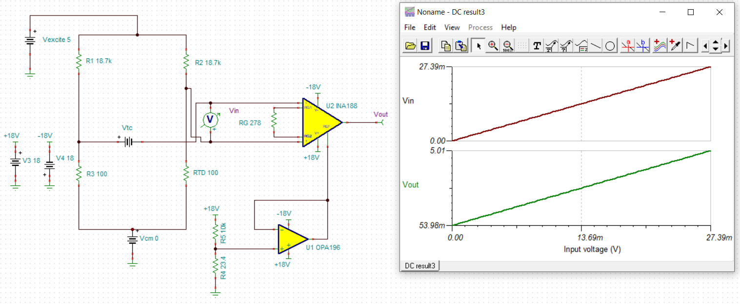
Reading the TIDUBA5.pdf, I see the reference design simulation results in figure 5, show the output at near 5 volts when the output of the thermocouple is -2.5mV and the output decreases as the thermocouple output, (and temperature), increases. Seems unusual for the output to change inversely to the input. This is opposite of the AD596. The first thought is to switch the inputs on the INA188, and then I believe I would need to adjust the gain because the AD596 outputs -500mA at -50°C and 5 volts at 500°C.


Is it possible that someone has an apnote that addresses this? Can you offer any assistance or advice?

Thanks,

Brian 

  • Hi Brian,

    Thanks for your post. This can be done by switching the inputs and adjusting Vref to 637.099mV. See attached for the TINA sim.

    TIPD209 Vtc sweep - ta edit.TSC

    -Tamara Alani

  • AD596AHZ.pdfMy customer is having issues with being able to posts to e2e.  While I'm looking into that for him he asked that I post this reply:

    I looked at the input and the output of the Tina circuit; 27.388mV in, 5 volts out; this matches the AD596 datasheet.

    I changed the input to several other thermocouple mV values from the AD596 datasheet, but the output of the Tina circuit did not match the output of the

    AD596 datasheet.

  • Hi Jarrett,

    Following the TIPD209, I edited the TINA file to the following: an input of -2.431mV to 27.393mV yields a linear output of 250mV to 5V:

    What is your customer's input / output requirements? We can tweak the TINA sim accordingly.

    -Tamara

  • The bug has been corrected and I am now able to post.

    Please refer to the datasheet of AD596AHZ.

    If I change the J-type thermocouple voltage in the Tina circuit to a value from Table I of the AD596 datasheet, the output of the Tina circuit does not match the expected output of the AD596 in the Table.

    For example at 25°C, thermocouple voltage is 1.277mV; the output of the Tina circuit is 850.95mV; from Table I the output of the AD596 would be 285mV.

    At 100°C, thermocouple = 5.268mV; Tina output = 1490mV; expected output of the AD596 from the Table, 1006mV.

    At 500°C it is correct, thermocouple = 27.388mV; Tina output = 5000mV; AD596 output from the Table, 5000mV.

     I have bare boards and parts ordered. I will build up the circuit and compare it to Tina and the AD596 circuit board that we have been using.

    I’d like to get as far as possible before building the circuit.

    My goal is to move away from using the older Analog Devices part to a new circuit with TI components.

     Thank you,

    Brian Buehl

  • In case that it was not clear in earlier posts, I would like to duplicate the output of the AD596AHZ so that the new board will be software compatible with the old board to allow replacements on any machine we have made in the past 25+ years. We would also use the new board with the existing software for current production.

  • Hi Brian,

    I understand now. The TIPD example uses a different thermocouple with its own min and max differential voltage. It looks like the AD596 has a wider differential voltage: -1370mV at 200C to 7689mV at 750C.

    What is your expected temperature range? This way I can recreate the sweep with the new thermocouple. I will need to adjust the reference voltage.

    -Tamara

  • Wee need to measure from 0 - 500 C

  • Hi Brian,

    I captured the expected input voltage ranges for temperature 0-500C of the datasheet:

    When Vin = 0V, we want Vout = 54mV

    When Vin = 27.388mV, we want Vout = 5V

    Because we need a minimum of 54mV on the output of the INA, we have to configure the INA in split supply of +/-18V. Single supply would not allow us to swing that close to the rail.

    See the edited sweep attached. I hope this answers your question.

    7345.TIPD209 Vtc sweep - ta edit.TSC

    -Tamara

  • Yes, the output matches the AD596. Would the output be able to get to 54mV with a split supply of 12 volts or does it need to be 18?

    I have +5 and +12 and will need to generate any additional voltages on the board. I'm looking at a charge pump that will get me -12.

    Thank you,

    Brian

  • Hi Brian,

    Certainly, +/12V supplies should work.

    Happy to help.

    -Tamara