A related question is a question created from another question. When the related question is created, it will be automatically linked to the original question.
If you have a related question, please click the "Ask a related question" button in the top right corner. The newly created question will be automatically linked to this question.
Part Number: INA233 Other Parts Discussed in Thread: ISO1541
Hi Team,
There are a lot of registers and what is the fundamental registers that must be configure in order for INA233 to work properly? I just want to read the current and voltage from INA233 only.
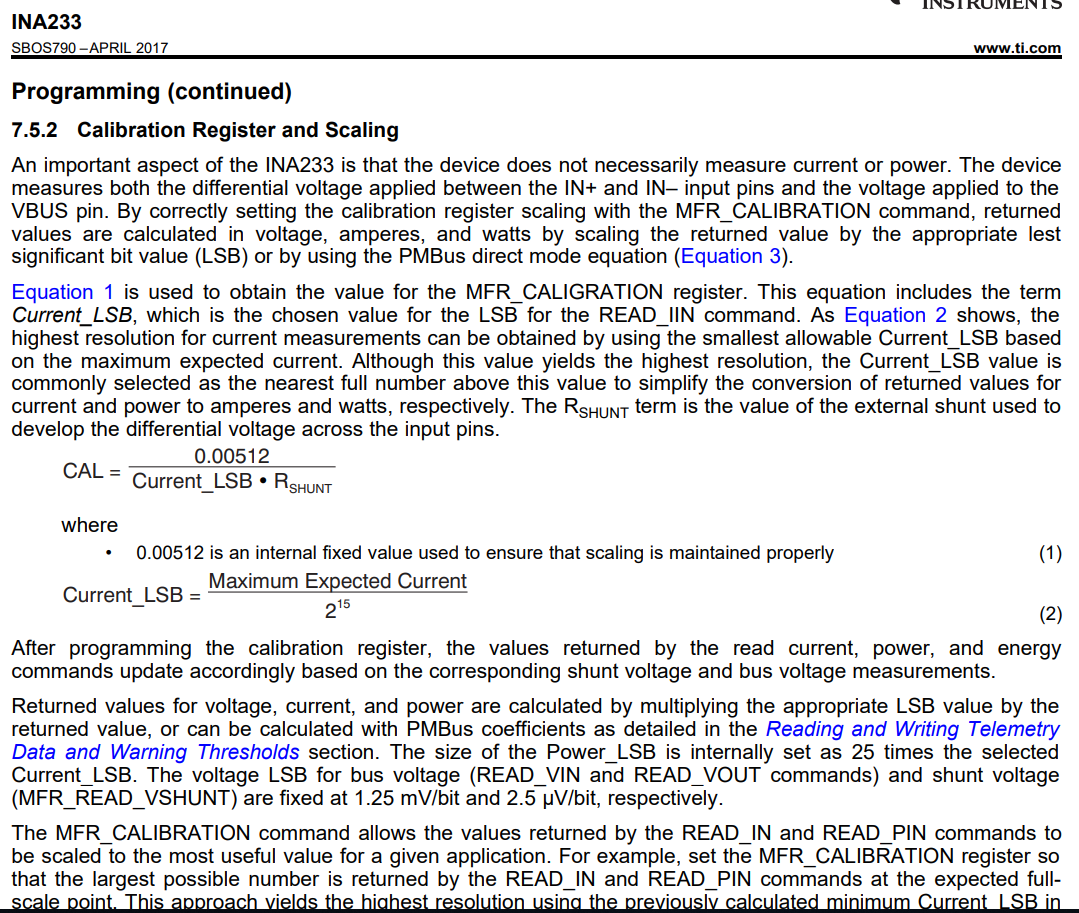
If you want the INA233 to read back current values, then the MFR_CALIBRATION PMBus command (D4h) must be executed once after every power reset. In Table 4 all of the PMBus commands are listed and these can be thought of as just registers.
Programming the MFR_CALIBRATION register gives the device what the shunt resistor value is along with some scaling so it can perform the calculation internally.
After programming D4h, the INA233 will begin generating current and voltage measurements immediately because this is its default programming according to the default value of MFR_ADC_CONFIG (D0h).
You obtain current and voltage measurements from codes 89h and 88h respectively.
Equations 1 and 2 of datasheet show how to calculate this value. There is also an example calculation in the applications section of the datasheet. You need to determine the maximum current you will measure in your application to set a current LSB.
Could you zoom into the 8th and 9th clock cycles? It seems like once INA233 takes control of SCL is supposed to hold SCL low (ACK), it stops at ~0.9V.
Would you be able to explain why the 8th and 9th SCL clock pulses from master are so close together? Maybe this is violating the t_SUDAT (data setup time) of INA233.
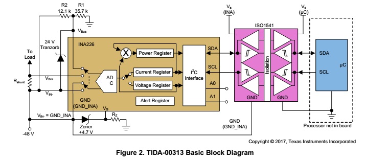
Are you also taking into consideration the threshold voltages of the ISO1541? The testing conditions for the low-level output voltages show the SDA and SCL currents greater than 0.5mA; however, your bus voltage seems to only reach 4V. With the 10kOhm resistors this equates to 400uA and is not a valid condition for the device.
I would recommend attempting communication without the ISO1541. If this does not fix the issue, then I would reduce the pull-up resistance to 4.7kOhm. If this does not work, try understanding why the master’s 8th and 9th SCL cycles are so close. Perhaps this could be a firmware fix.