This thread has been locked.

If you have a related question, please click the "Ask a related question" button in the top right corner. The newly created question will be automatically linked to this question.

OPA333: Hi, I have a question about OPAMP stability tina simulation.

Part Number: OPA333

Hi,

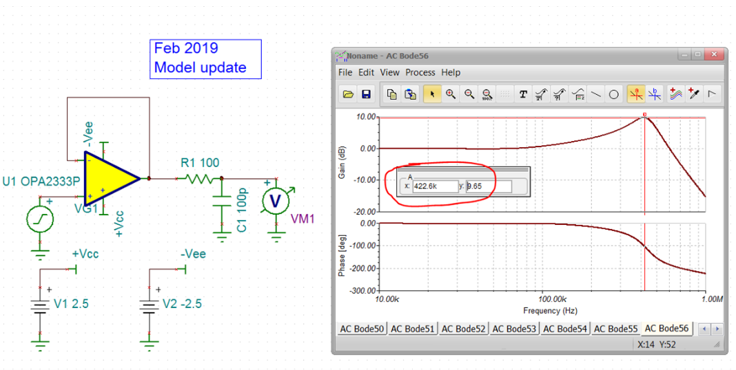
I am trying to simulate buffer stability with tina.

To get a transient graph, I used circuit above and got pretty good result.

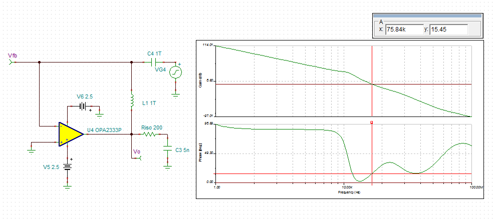
But in TI precision lab, I learned that if i want to simulate gain and phase margin, i have to use open loop circuit like below.

Why do i have to design circuit like above?

If i simulate with first circuit, will i get a wrong result?

Thanks,

Best regards,

Yunsik

  • Hello Yunsik, 

    Make sure you are using the most recent TINA model, there was a Feb. 2019 update, running closed loop AC shows almost 15dB peaking, going to Figure 2 in this article suggests that is <10deg phase margin, 

    https://www.planetanalog.com/author.asp?section_id=3404&doc_id=565056

    The LG sim circuit you show is often adequate, however, if the output impedance is well modelled (one of the updates in the models) it is isolated from any feedback load in that approach. Won't matter in your buffer circuit but sometimes makes a big difference with feedback caps. HEre is a slightly more accurate LG sim, this actually says we are past 180deg - 

    There is not much in the data sheet on Riso vs Cap load,but just iterating in the LG sim -even pretty high Riso did not make much difference, If you need to drive a 5nF, you probably need to use the dual loop approach, 

  • Thank you for your reply, Michael!

    But I am still confused. is it correct if i say first circuit's phase margin is 25.25 (180-154.75) and second circuit's phase margin is 40.43(180-139.57).

    I want to calculate phase margin from phase bode plot not from gain peaking.

    Also, in first circuit's phase bode plot, why does phase go to positive side?

  • My LG sims were showing the first circuit is way unstable, not sure why the closed loop does not show that. with 200ohms is still unstable my LG sim, I tried the 2011 model,same thing. I just don't think this circuit can drive 5nF successfully. I did try some more reasonable cap loads and things start to make sense again, here is closed loop 100pF with 100ohm Riso, still peaking pretty badly, 

    So, again, that 9.5dB peaking at 422kHz suggests a LG=0dB crossover near that frequency with only about 18deg phase margin from the Figure 2 in the article I sent previously - here that is, now this is matching better making more sense, that 5nF is probably interacting with the open loop output impedance in the model to move off this simple analysis - Understanding the sims is one thing, but I don't think this part can drive 5nF successfully in the simple Riso approach, 

  • Yunsik,

    The second circuit with 1T inductor and 1T capacitor is obviously ONLY for analyzing stability of the first circuit using rate of closure method - thus, the actual circuit is your first circuit.  1V step overshoot does NOT tell you anything about the stability of the circuit - you must use a small signal of tens of mV, not higher, so the input stage operates linearly instead of slewing.

  • Micheal,

    You looking at the wrong node - in order to determine stability of the circuit, you must look directly at the output of the amplifier and NOT on the right side of isolation Riso - VM1. With no Riso resistor, the phase margin is -10 degrees so the circuit is totally unstable (sustained oscillation).

    Notice, you must look at the phase margin at the frequency where AOL and 1/beta curves intersect (loop-gain is zero) - see below.

    Using 200ohm Riso resistor, result in 15 degrees phase margin where the circuit is marginally stable (ringing with long settling time) for a typical part used in the macro-model BUT may become unstable over process variation where phase margin may drop by up to 20-25 degrees due to increase in the bandwidth.  

    For that reason, in order to assure unconditional stability of the circuit over process variation, we recommend the design to have at least 45 degrees phase margin so in case of phase margin decreasing by 25 degrees due to process variation there is at least 20 degree phase margin left to guarantee stable operation.   For 5nF load, this is accomplished with 500ohm Riso resistor - see below.

  • No Marek, I am looking in the right place, I just do this slightly differently

    1. Feed in test signal on the inverting input after the cap shorts out

    2. Connect the feedback circuit going back outside the inductor that sets DC operating point

    3. Add the internal input C at the summing junction, 

    4. Sense the Aol*Beta at the inverting junction - with the inversion driving into the inverting node, putting that sense with the positive side on the summing junction reports phase margin directly - and yes, I get the same -10deg you do, 

  • Michael,

    I referred to your first gain peaking simulation (see below) looking at the wrong node - VM1 instead of on the left side of R1 resistor.

    Your second simulation shown above is correct and results in the same -10 degrees phase margin for no Riso resistor as my simulation.

  • Oh your'e right, I need to be on the output pin before the RC filtering, let me try that again, didn't change much, but yes that is the place to look to relate to LG phase margin,