This thread has been locked.

If you have a related question, please click the "Ask a related question" button in the top right corner. The newly created question will be automatically linked to this question.

TLC2652: TLC2652 external capacitors tied to VDD-.

Part Number: TLC2652
Other Parts Discussed in Thread: OPA188, OPA189, THS4001

Hi,

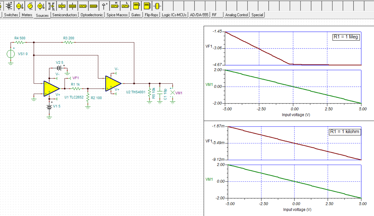
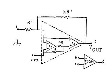
I am using TLC2652 in a composite circuit wherein the Cxa and Cxb are connected to VDD- as per datasheet.

The circuit is as shown below.

I am observing the output to be -2.5V with -5V input voltage with the Cxa and Cxb connected to VDD-.

But i am able to get the output as 2V if the Cxa and Cxb are grounded.

Need suggestions for the same.

Thanks

Pavithra Joshi

  • Hello Pavithra,

    Composite Op amp amplifiers can be more challenging to get operating correctly and stabilized when compared to more conventional Op amp amplifier circuits. I am not familiar with the particular composite amplifier configuration that you have chosen, but lets assume that it is a proven design.

    The TLC2652 is a 30+ year old chopper and the only information we have about the device is the datasheet. The datasheet in the Theory of Operation section describes the function of CXA and CXB and indeed shows the lower side of the two capacitors being connected to VDD-. It is not really evident why moving the capacitor connections from VDD- to ground remedies the operation so something else about the composite circuit may be the issue. If you were to connect the TLC2652 up by itself you may find it behaves as expected.  

    A circuit point that caught my eye is the R5 - 1 Meg, R3 - 100 Ohm divider at the output of the TLC2652 in your TINA diagram. When I set the circuit up in TINA I find that the TLC2652 output is being driven very close to, or into its negative output swing rail when the input voltage is swept from -5 V to +5 V. You can see in the upper plot below that when the input voltage is near 0 V, or higher, the output voltage hits the negative swing rail. That isn't happening when the input voltage is -5 V, but it might be an indicator of the issue. 

    When I reduce the value of R1 in my TINA schematic from 1 Meg, to 10 kilohm, then to 1 kilohm the TLC2652 output moves further and further away from the negative supply rail, and more into the linear output voltage range. The second, lower plot above shows the TLC2652 output voltage with R1 set to 1 kilohm. You may want to try reducing the R1 value in your circuit and see if the CXA and CXB connection to VDD- then results in the expected behavior.

    As mentioned, the TLC2652 is a not a modern chopper Op amp. There are much newer, higher performance chopper Op amps that do require the external CXA and CXB capacitors. I suggest trying one of them in your circuit. The OPA188, or OPA189 would be some options:

    http://www.ti.com/lit/ds/symlink/opa189.pdf

    Regards, Thomas

    Precision Amplifiers Applications Engineering

  • Hi Thomas,

    I tried again with the Cxa and Cxb capacitors tied to VDD- and the output is as expected.

    I just followed this composite circuit suggested in a very old document.

    This is different from the TI suggested composite structure.

    I just wanted to know whether high speed as THS4001 and low precision of TLC2652 can be achieved with this.

    Thanks

    Pavithra Joshi

  • Hi Pavithra,

    The simulations indicate that conceptually the TLC2652, THS4001 combination functions in the compound amplifier circuit you provided. The two Op amps are very different from each other, one being a legacy chopper and the other being a wide bandwidth, high current output amplifier. The TLC2652 simulation model is simplistic by today's standards, and I can't speak about the THS4001 model because it comes from a different TI amplifier group. Therefore, the modeling may not show some potential problem such as stability.

    The next step is really to try the circuit and see if it provides the needed performances.

    Regards, Thomas

    Precision Amplifiers Applications Engineering