This thread has been locked.

If you have a related question, please click the "Ask a related question" button in the top right corner. The newly created question will be automatically linked to this question.

LMP7721 : OPA320 -> OPAMP selection for use case comparable to SBAA242A?

Part Number: LMP7721OPA320
Other Parts Discussed in Thread: TINA-TI, OPA320, LMP2234, ADS1248

Team,

Can you please help for choosing the appropriate OPAMP for the below use case (just the OPAMP portion for now).

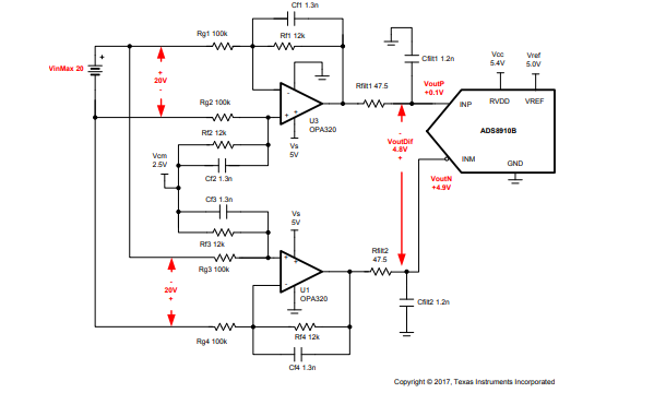
The goal is to be able to measure precision as close as 2mV on a +/-10V VDC source across the complete range (see SBAA242A - see data converter cookbook page 71) but it must have as well a high input impedance (>= 10MOhms). In SBAA266A - see Data converter cookbook page 131 it is mentioned that a low bias current OPAMP should be used for system that have high input impedance.
Note that the two GND  (+/-10VDC and the measurement side) are not connected together.

-Would the LMP7721 (as shown in SBAA266A) work as well for SBAA242A with an high input impedance (for example using Mohms resistor instead of 100kohms)?

-Early testing show 2 to 3 mV when inputs are at the same potential (ie 0V diff).
What if the main effect/factor that gives this results when the inputs are at the same voltage level?
Is there a way to compensate for this?

-When input is at 2V then the measurement errors goes to 6 to 7 mV.

More generally:
What do you advise to use as OPAMP for this use case?
What would be the main factors to consider for selection that will have the most infuence on the error?
Would it be possible to share a TINA-TI model for this use case (if model is available for the OPAMP you advise to use)?

Thanks in advance,

A.

  • Anber,

    OPA320 is optimized for driving ADC converters while LMP7721 IB is meant to be used for high output impedance sensors like pH probes in order to minimized error due to the input bias current.  OPA320 typical IB is 0.2pA at 25C and max 50pA at 85C so the maximum input referred error due to 1Mohm resistor would be 0.2uV or 50uV, respectively.  Having said that, in the configuration shown below the IB related input voltage error is a function of the parellel combination of the input and feedback resistors, Vos(IB) = IB*(Rin||Rf), so for all practical purposes the input error would be the same using 100k or 1Mohm because 12kohm would dominate it.

    All in all, I would recommend you to use OPA320 in your system.

  • Hi Marek,

    Thanks for this information but could you explain to me why OPA320 it's a better choice for driving ADC converter than LMP7721 ?

    Another point, my system need to have an internal input over 10Mohm. I think i have only two way to do that :

    • use bridge divider to have input impedance around 10MOhm and change Rg||Rf ratio to have a gain off 100. Rg||Rf impedance would be 100kOhm
    • change Rg||Rf to have input impedance at 10MOhm with a 0.2 gain.

    I think the first solution is better, what did you think ?

    It is possible to replace OPA320 by LMP2234 ? I need to have a low power consumption.

    Thanks for your help

    This afternoon I have tried the schema above. With OPA320, Rg = 2Mohm, Rf = 1Mohm and ADC = ADS1248.
    Voltage measured on bridge divider; Rbot = 2Mohm, Rtop = 10Mohm.
    Input wire are connected together but I have a drop voltage on Rbot = 1mV and I have 10mV in input of the ADC.
    Did you have an idea why I measure ten times the theorical value ?

  • In order to drive ADC, op amp's settling time is critical since it must be able to settle quickly current charge injection coming from the closing/opening of ADC Sample and Hold switch.  OPA320 settling time is 0.5us to 0.0015% (16-bit resolution) while settling time of LMP7721 is slower (not specified).  A settling time is a direct function of the op amp bandwidth and slew rate, which are directly proportional to the quiescent current, IQ.  For that reason, there is no way to replace 20MHz OPA320 with 130kHz LMP2234 unless you use 8-bit converter. However, since you try to obtain 2mV precision on 10V range, this requires at least 16-bit converter – therefore, depending on the sampling frequency you may be able to use in your application LMP7721 instead of OPA320 but NOT LMP2234. 

    What input resistor you may use is driven by the required gain and dc error related to IB; thus, first you need to fully understand the application in order to decide whether you need a gain of 100 or attenuation of 1/5.

  • Hi,

    How did you do the relation between settling time and ADC bit resolution ?
    In my application I need to have an acquisition at 5SPS. LMP2234 Slew Rate = 48V/ms, so to do 0V-2V I need 41µs. With an acquisition time at 200ms I think it is possible to use this AOp. Or I forget something ?


    I need to measure 10V with accuracy at 1mV (not 2mV), so amplifier error must be under 100µV
    If I use an OPA320 with IB = 0.2pA, Rg||Rf must be under (100µV /5)/0.2pA = 100MOhm. But when I test with Rg||Rf = 2Mohm||1MOhm, output voltage = 10mV but input = 0V.

    Is ther another parameter to consider to select gain resistor ?

    Thanks

  • I calculated ADC resolution from the error bands of the settling time and not settling time itself. A precision of 0.0015% represents 1/0.000015=66,666 number of bits, which means 0.0015% of the full scale correlates with ~1 LSB of 16-bit converter (2^16=65,536).

    In terms of speed, you should not have a problem using LMP2234 for an acquisition at 5sps (almost DC) but the required precision may be a challenge. Since the max Vos of LMP2234 alone is +/-150uV (+/-230uV over temp) and you must also include integrated 60nV/rt-Hz broadband noise (~27uVrms) and up to 206uVrms thermal noise of 100Mohm resistor (46uVrms for 1M||2M resistor), I don’t think you can get a total error under 100uV even if you use heavy filtering.

  • Thanks for the information about ADC

    Why do you consider the input voltage noise density and how do you find 27µVrms ?
    With input DC voltage I only keep noise voltage? 2.4µVpp for LMP2234.

    Thks

  • No, that is not correct. 2.4uVpp input noise covers only 0.1 to10Hz low frequency noise but your bandwidth is much higher than 10Hz - see below.

    Thus, you must also consider thermal noise of the resistor used, Vnr=(4*K*T*R*BWn)^0.5, as well as high frequency (broadband) noise, which is a function of circuit configuration - in other words, you must integrate the broadband (60nV/rt-Hz) spectral density noise across the noise bandwidth, BWn: Vn_broadband = Vn_density*(BWn)^0.5 = 60nV*(130,000*1.57)^.5 = 27uVrms.  Please review TI Precision Labs training course discussing the topic of different type of noise under following link: 

    https://training.ti.com/ti-precision-labs-op-amps

  • Thanks for these explanations, it helped me a lot to define AOp error.

    I had change my electric circuit and for the moment I have better result with LMP2234. With good filter noise is limited to +/-300µV

  • Hello Gregoire,

    We haven't heard from you in a while, we hope we were able to resolve your issue. I am going to close this thread now. Feel free to reply if you have any questions moving forward with this design.

    -Tamara