This thread has been locked.

If you have a related question, please click the "Ask a related question" button in the top right corner. The newly created question will be automatically linked to this question.

LM2903: Design check

Part Number: LM2903
Other Parts Discussed in Thread: TLV1701, TLV1702, TLV7041, TLV7031

Hi Sirs,

Sorry to bother you.
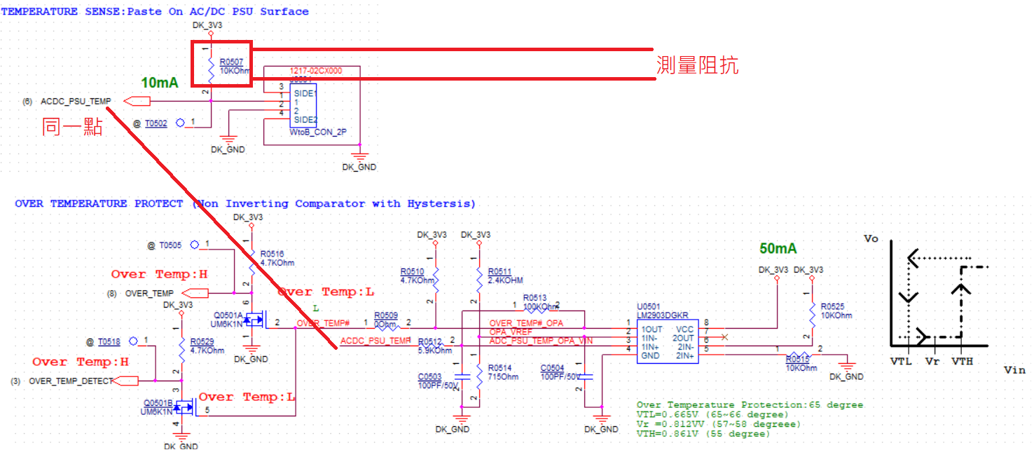
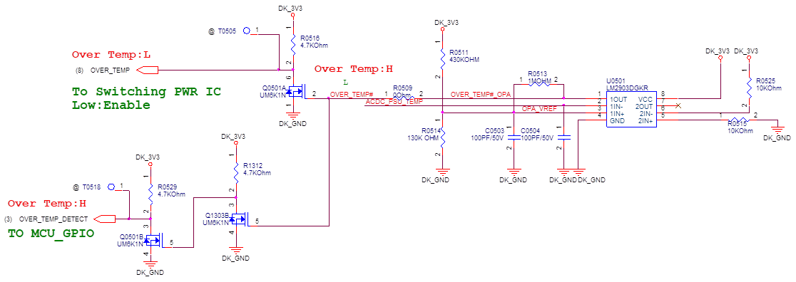
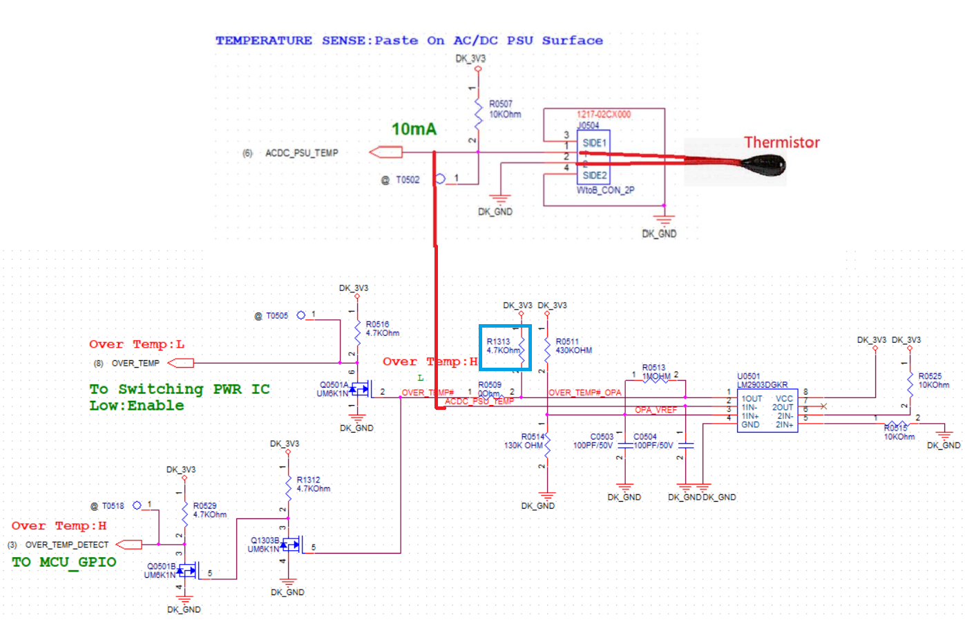
We measure the impedance of R0507 is 9.137Kohm.

We think that because it's paralle OUT of the OPA
The OPA out is the ideal voltage VCC.

So the direct measurement of the impedance of R0507 will be 10Kohm parallel (5.9Kohm with100Kohm) to calculate, get the impedance of 9.137Kohm? Am i wrong?


We also like to know are there other better design for us?

  • Shu-Cheng,

    I'm trying to understand your circuit a little more clearly before answering, what is the device that is connected to R0507 and the 3.3V pullup?

    Is R0507 a thermistor?

    Regards,

    Jonny

  • Hi Sirs,

    Thanks for your reply

    R0507 is a general resistance, the J0504 is externally connected to the NTC Thermistor of 10K Ohm.


    The architecture is as follows:
    We infer whether the output is the ideal voltage VCC due to the characteristics of OPA.
    Therefore, the equivalent impedance of ADC_PSU_TEMP to DK_3V3 is R0507//(R0512+R0513), so it is 9.137Kohm?
    However, this will cause the MCU reading voltage to be biased, resulting in inaccurate temperature.

    Ex:
    Normal temperature 25 degree, R0507=10K Ohm, NTC Thermistor=10K Ohm, MCU ADC read voltage value is 1.65V
    However, since the equivalent impedance of ADC_PSU_TEMP to DK_3V3 is 9.137Kohm, and the voltage division of NTC Thermistor=10K Ohm, the voltage value read by the MCU ADC is 1.72V.
    That will cause the partial pressure value <-> temperature mapping is not accurate

    So is there any other better suggestion for our design?

  • Shu-Cheng,

    Thanks for the description, that helped clear things up for me. Instead of using just one channel of the LM2903, you could use the second channel and set it up as a window comparator.

    Please take a look on this application guide on window comparators: http://www.ti.com/lit/ug/tidub01/tidub01.pdf

    Meanwhile, I designed a circuit in TINA to try and meet your VTL/VTH thresholds. Unfortunately we do not have a proper TINA model for the LM2903, but I used the TLV1702 (Tied two TLV1701 together) which is a high voltage open-drain part. The inputs are rail to rail in this device, however the design will not violate the LM2903 common mode. Let me know what you think of this suggestion. The resistors I used are not standard values so you will have to adjust these as necessary.

    In this design, when the voltage is between 0.665V and 0.861V, the output of the comparator will be pulled up to 3.3V. Outside of this window, the output will be grounded.

    Regards,

    Jonny

    LM2903_Thermistor_WindowApplication.TSC

  • Alternatively,

    You can set up the device in an inverting configuration. This way the hysteresis network won't bias any impedances seen on your input signal. I made a simulated circuit using the TLV7041. You can still use LM2903 here, but the TLV7041 is our go-to low voltage, micropower, rail to rail part:TLV_7041_Inverting_ThermistorApp - autosave 19-08-20 13_20.TSC

    Regards,

    Jonny

  • Hi Sirs,

    Thanks for your help.

    Could you help us to double check below?

    How about change R0513 to 1M Ohm and R0512 to 59K Ohm?

    R0507//(R0512+R0513)=9.9K

    Ambient temperature:25 degree, NTC thermistor is 10K Ohm.

    3.3V*9.9K/(10K+9.9K)=1.64V

  • Shu-Cheng,

    As long as you are ok with the slight inaccuracy caused by the 9.9k equivalence, 

    I would actually suggest changing R0512 to 60.4kohms instead of 59kohms. I am getting slightly more accurate results with this value.

    Also, I would suggest changing your resistor dividers R0511 and R0514 to something in the 100kohm or Mohm range (3.09Mohm for R0511 and 1M for R0514 ). You will be burning alot of current through your resistor dividers with your current values.

    Regards,

    Jonny

  • Hi Sirs,

    Thanks for your reply.

    We still have question window comparator.

    We would like below behavior.


    When Vin is ≦VL, Vo=L.

    When Vin increased≧VH, Vo=H

    The behavior of window comparator is:

    Vo=High, If VL≦VIN≦VH

    Vo=L, if otherwise.

    I think the behavior is different.

    Do you have any other design suggestion to instead of Non Inverting Comparator circuit?


    Thank you.

  • Shu-Cheng,

    Thanks for sharing what you want to achieve in your application. 

    We could achieve the output you described in the first image above- however the output will be inverted as in:

    • When Vin is ≦VL, Vo=H
    • When Vin increased≧VH, Vo=L

    By setting the comparator up in an inverting configuration, the hysteresis network will not change the impedance of the biasing resistor to your thermistor and you would get more accurate results (if you are ok with this type of implementation).

    Otherwise, I think the best option would be to change the value of your biasing resistor to the 3.3V supply to a Mohm impedance- the drawback being the accuracy isn't as precise.

    Regards,
    Jonny

  • Hi Sirs,

    Thanks for your reply


    How is the suggestion design about below? Using Inverting Comparator with Hystersis?

    I think we can use MOSFET to inverse it back.

  • Using a mosfet to invert the output of the comparator would be a clever trick.

    Is there a reason why you would like to use the LM2903? Would you be open to other options?

    It seems like you are not using the second channel on the device. Also, I noticed that all of your supply rails in your schematic are the same, so a push-pull device would be able to achieve the same result. You could use that pullup resistor as your drain load for your inverter instead :) 

    I would recommend taking a look at the TLV7031, which is our low voltage nanopower push-pull comparator. It comes in leaded or space-saving leadless options, and could allow you to conserve more power than the LM2903. There is also an open drain option (TLV7041) if you would like to stick with an open drain part.TLV7031_ThermistorApp_Inverter.TSC

    I've attached a schematic using the TLV7031 to meet your Vtl/Vth specifications. Please let me know what you think of this possible solution.

    Regards,

    Jonny

  • Hi Sirs,

    Thanks for your reply

    Please refer our reply as red word.

    So did you have more suggestion for us?

    Is there a reason why you would like to use the LM2903?

    Actually, we don’t have a special reason for using LM2903.

    We just consider below:

    (1)LM2903 is implemented of our rev_1.0 design, and we can rework it for verification before next phase.

    (2)Material preparation.

    (3)Does it already exist PEGATRON part number?

    (4)We have to explain to our customer why change LM2903 to TLV7031


    It seems like you are not using the second channel on the device.

    Yes.


    By the way, 

    Do you recommend us to change using TLV7031 because below reasons?

    (1)Low voltage nanopower push-pull comparator

    (2)We only use 1 channel. Using TLV7031 to save spacing and cost.

  • Yes,

    I believe your design suggestion should work for the application.

    We created this document to help design inverting hysteresis: SNOA997_TLV7031.pdf

    Feel free to use it to help with your design.

    Regards,

    Jonny

  • Hi Sirs,

    Thanks for your reply.

    Sorry to bother you again.

    We used LM2903DGKR and rework it to Inverting Comparator with Hystersis. Please refer below sch.

    We tested it and get below result.

    When Vin(ACDC_PSU_TEMP)<VTL, OPA out is high. The output of OPA is only about 0.7V. Is it because LM2903DGKR not a  push-pull comparator?

    I add/stuff R1313(please see below blue mark).

    When Vin(ACDC_PSU_TEMP)<VTL, OPA out is high. The output of OPA is about 3.3V.

    Our original issue:

    Using non inverting comparator with hystersis and  the output is the ideal voltage VCC due to the characteristics of OPA.

    Therefore, the equivalent impedance of ADC_PSU_TEMP to DK_3V3 is R0507//(R0512+R0513), so it is 9.137Kohm. It’s not 10K Ohm

    When we use below inverting comparator with hystersis design, The equivalent impedance of ADC_PSU_TEMP to DK_3V3 is R0507:10K Ohm.

    We just want someone can help us check and confirm it.

    Many thanks!!

  • Shu-Cheng,

    Yes, in your first image you provided, the output only reached 0.7V because the comparator has open drain output and requires a pullup resistor to operate correctly. Be sure to note that having a pullup resistor will affect your hysteresis network slightly. Take a look at this newest cookbook for designing inverting comparator hysteresis: http://www.ti.com/lit/an/snoa997a/snoa997a.pdf

    Referring to your previous post, you could absolutely use the TLV7031 in this application for its space saving and cost. Sorry I missed that previously.

    Regards,

    Jonny