This thread has been locked.

If you have a related question, please click the "Ask a related question" button in the top right corner. The newly created question will be automatically linked to this question.

INA240: Real output not linear, Spice predicted linear

Guru 54057 points
Part Number: INA240
Other Parts Discussed in Thread: INA282,

Previous thread last two Tina models, indicate linear output via REF=GND. However the real output is not as linear and crosses 0V >-21mV. Also the idle Real 3 output/s got real quiet <6mV noise, very impressive. Oddly REF=GND is not controlling Real differential amp/s linear region as Tina Spice model indicates it does very well. Point being how can we trust the Spice results when 240 Real results do not produce the same linear output? Asked last thread what would be a better circuit configuration to produce better linear region of the entire shunt signal (REF=GND) as plots indicated possible for (-IN=510k)?

Scope capture of Real linear results below differs greatly from Spice projection! Yet output signal has the full ± (expected) signature not being produced via -IN tied directly to ground. Oddly modifying center & last sensors respectively reduced the digital output to more closely match an DC supply 100A bar (external) digital current monitor. When 3 sensors were modified (-IN=510k) the digital results were way off from external monitor digital readout and 3-240's could not detect rotor loading other than by PWM drive due to the non-linear output signal (1st,2nd captures). It would seem from Spice versus Real testing the 240 has production issues not being checked for after manufacture! Tina model used a sine wave current generator to produce excellent linear results (-IN=510k) versus Real captures below of sharp pulsed PWM signal driving the input. 

Real results CH1=shunt, CH2=240: Note shunt ± (current) signature is very much present but not so linear as Spice predicted. Note also the distinct current envelope is not broken up as via -IN=GND (last capture).

-IN=GND:

  • The biggest difference to note between (-IN=GND) & (-IN=510k) is the output level (V/A) reduced to 100mV, well below Spice linear prediction. The last capture CH2=700mV  actual 40mV/A=17.5A peak, 100A bar DC supply current monitor indicated 8.2A- 8.5A. Even adjusting 2mohm shunt for 3mohm, note the last capture CH2 is seemingly missing 1/2 the current cycles shown (1st/2nd) captures.

    Several plots up to 50A 3 current generator (50A) waveforms (20KHz) for -IN=510k tied to ground.

    See post below:

  • Hi BP101,

    The link you provided is shown as TDR archive. Can you collect the individual files into a folder and simply zip the folder?

    Regards, Guang

  • Guang Zhou said:
    The link you provided is shown as TDR archive

    So what is the problem,  unzip file put it in any folder and open it in Tina transient analysis plot viewer. I do this all the time with analysis plots for future reference. The plots are in order of linear output (0.5A-50A), last few plots are 3 different IN wave forms 50A current generator.

    Edit: Noticed 2mohm TDR was missing 0.5A (1st plot) 20KHz square wave (+IN signal), -IN=510k to GND. 

    Added another TDR file (noted) 5mohm shunt: /cfs-file/__key/communityserver-discussions-components-files/14/7610.INA240A1_2D00_510k_2D00_IN_5F00_20KHz_5F00_2_2D00_5mohm.zip

  • Hi BP101,

    When simulation and reality don’t agree, I would look into setup differences. List the setup side by side and compare. An example - did you capture the input current to make sure it really is a linear 0.5 to 50A as you assumed in simulation?

    Regards, Guang

  • Guang Zhou said:
    did you capture the input current to make sure it really is a linear 0.5 to 50A as you assumed in simulation?

    I don't think you understand the 1st/2nd captures above post are not what Tina predicted for the very same HW configuration. The steady state current in CH2 first capture (8.2A) clamps to 0V when Tina model/s predict AIN0 does not clamp nor cross 0V. Same is true for Tina 50A plot, AIN0 never clamps to 0V.

    That seems to be no matter how -IN is configured in Tina model the output remains linear to the ±IN signal even when it crosses 0V. Goes to reason 240 is not level translating ±IN above ground as IG1 does in Tina transient analysis. Rather 240 incorrectly clamps -IN to ground, Tina 240 does not how can that be as we based all configurations on Tina model via IG1?

    So we need to see the 240 produce the current signal (1st/2nd CH2 captures) and not be clamped to 0V, rather rise above 0V as CMV magnitude increases. That is current measurement any ADC can easily extrapolate linear slope or ramp into steady state average.

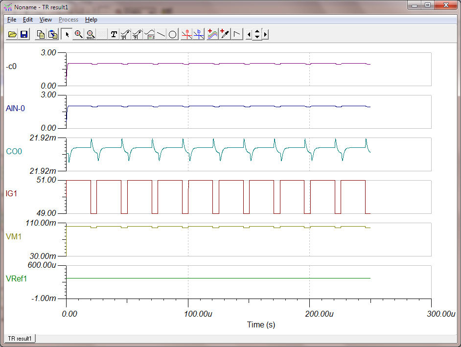
    Like this plot (-IN=GND), (REF1,2=GND), 2mohm shunt, Note: ANI-0 is not clamped to 0V as Real 240 incorrectly does.

  • Hi BP101,

    Please attach your TINA circuit.

    Regards, Guang

  • Hi BP101,

    You have the differential input set to 100mV in simulation, of course the output will be 2V.

    In case of PCB, is the current between 49A and 50A, as in simulation? Like I questioned previously, have you done the homework to make sure setups are identical between sim and reality?

    Regards, Guang

  • Guang Zhou said:
    You have the differential input set to 100mV in simulation, of course the output will be 2V

    IG1 is set to 50A and IC (initial condition) is 30mV  there is no shunt voltage other than what IG1 produced CMV across R11.

  • When we change IG1 to 10A or even 0.5A and the output AIN0-0 increased in a linear steady state as expected.

  • Hi BP101,

    I understand that the output is correct for anything above 0A, sim or otherwise.

    What I’m asking is, again --- is it the same in reality? In other words, is the current indeed above 0A all the time? Have you made sure you’re simulating a real world situation?

    Regards, Guang                                          

  • Guang Zhou said:
    In other words, is the current indeed above 0A all the time?

     Inductive current never drops to 0A or is otherwise clamped to 0A like the Real 240 output it behaving. Once a motor is running inductive current is always >0A. 

  • Hi BP101,

    I’d love to hear more about your theory that the current is always >0A. Can you please explain in more detail?

    Regards, Guang

  • There Tina indicates correct current behavior via (IGI). Yet the Real (3rd capture) is being clamped to 0V and omits 1/2 the polarity cycles. Inductive current fluctuates in polarity well above 0A as Tina 50A plot indicates. Motor will likely never see 50A in steady state for very long without tripping a fault condition.

  • Guang Zhou said:
    Can you please explain in more detail?

    Inductive current clamp gives a false perspective that current crosses 0A but only on AC channel does it seem that happens. Most all DMM can detect negative amps but do they randomly change polarity sign from (+) to (-) when placed inline with DC power supply. My Tenma 6000 count DMM never changes polarity sign unless the inputs are reversed. Then if probe inputs are reversed the polarity sign remains constant.

  • Hi BP101,

    DMM is not fast enough to show current change, what it shows is the average. You'll have to use a scope.

    Regards, Guang

  • Hi Guang,

    A shunt indicates voltage (CMV) sent into differential amp, not current flow. DMM would show 0A if current swings both positive and negative at the same momentum. Electrons once charged float in valance state only to accelerate or rapidly decelerate to a lower state but not to 0A. The DC inductive current I speak of exists at some higher level may fluctuate with polarity changes in that higher linear level, it does not ever come to a full and complete stop then change directions.

    Only AC current does that and this is DC current we are talking about, there is a difference between them.

  • Guang Zhou said:
    DMM is not fast enough to show current change, what it shows is the average.

    Tenma 6000 count DMM is True RMS (DC) amps indicates an average you mention. Hantek current clamp on inductor/s feeds detects rapid AC changes but represents DC current via scopes AC channel setting.  Yet that has nothing to do with why Tina Spice model plots and predicts a linear output from 0.5A to 50A and why the Real 240 does not when configured the very same way. I seem to have missed this issue in my initial investigation of the A2 REF being set to mid supply (1.65v) and output being restively divided.

    My gut tells me the ±IN PWM rejection some how affects differential amplifier level shift for CMV magnitude changes that Tina model is not constrained. Seemingly some part of shunt current flow should lift output off ground REF as Tina model output plots (prove). Also for proper ADC handling produce a liner rising (slope) output very similar to Tina 240 model. Oddly the addition of 510k to GND on -IN causes Real 240 to produce full ± DC output changes (first two captures) but oddly nothing changes for Tina model. The first two captures have Real PWM inductive current envelope but is missing linear DC rise above ground as Tina plots do produce. 

  • Hi BP101,

    Same question – do you know what the current really is?

    Regards, Guang

  • Guang Zhou said:
    Same question – do you know what the current really is?

    Not sure what you are getting at by asking that question but yes the external 100 amp bar DC supply current monitor is stable and Tenma True RMS both agree. Even if Tina model has two current generators (reversed 20KHz square wave pulse polarities) fed into +IN via shunt, the output remains above ground and very linear. Some how the Real 240 is not producing proper linear output for input signal with REF1,2=GND. The INA282 had roughly the same issue but past captures seem to indicate the very same sickness. 

    Typical configurations for high bandwidth Opamps monitor PWM current, feed output back into a resistor divider and into -IN input. This method below seems to produces a proper linear output for ADC single ended inputs similar to 1st two captures, see above posted signals. We are not supposed to have to add all these other passives around Opamp for the 240 to produce the correct linear output.  

  • Hi BP101,

    What I’m trying to get through to you is this – you need to make sure the input current is identical between sim and real world measurement. Then and only then can you make a claim that the results match or don’t match between the two. Otherwise any such claim is invalid.

    Also I hope you do realize that circuit is bidirectional while you configured INA240 in uni-directional, therefore clipping its output.

    I’m going to close this thread, please come back when you find out the real current input.

    Regards, Guang

  • Guang Zhou said:
    What I’m trying to get through to you is this – you need to make sure the input current is identical between sim and real world measurement. Then and only then can you make a claim that the results match or don’t match between the two. Otherwise any such claim is invalid.

    Perhaps we should not use Tina current generator to produce transient plots of linear output results? Tina current will never be exactly the same as Real since the Real circuit produces sloping current as the load increases into steady state over several seconds and Tina's IG1 jumps right into steady state <1us.

    Guang Zhou said:
    Also I hope you do realize that circuit is bidirectional while you configured INA240 in uni-directional, therefore clipping its output.


    Correct however we should be able to use/duplicate behavior for 240 to replace typical discrete Opamp current monitors as the data sheet implies. It would seem you are hung up on belief that inductive current is somehow always bidirectional, positive and negative in the same plot. The DC inverter sources Positive current from B+ to ground. Again real current fluctuates much like Tina's IG1 current generator plots, between 1-4 amps not -10A  -0- +10A that just ain't happening. If you are thinking it is bidirectional (-10 -0- +10) that would be an incorrect assumption on your part. We are taking about acceleration current in one direction and one direction only.

  • Guang Zhou said:
    you configured INA240 in uni-directional, therefore clipping its output.

    Umm the 1st & 2nd captures posted above REF1,2=GND and output clipping is not occurring (CH2), relative to ±IN waveform (CH1). When -IN is pulled above ground the output produces signatures of ± current fluctuations crossing the shunt, in one direction around an average. 

    We would like TI to advise proper value divider resistors & placements (-IN to GND) with perhaps a feed back to the Output for REF1,2=GND. That will create the correct signal for single ended ADC channels as the output is not clamped to ground each inductive current cycle. Both posted captures prove that assessment seems very correct and the 3rd capture CH2 is missing current cycles present on shunt via CH1!  

  • BP101 said:
    We would like TI to advise proper value divider resistors & placements (-IN to GND) with perhaps a feed back to the Output for REF1,2=GND. That will create the correct signal for single ended ADC channels as the output is not clamped to ground each inductive current cycle. Both posted captures prove that assessment seems very correct and the 3rd capture CH2 is missing current cycles present on shunt via CH1! 

    Attached file Tina 240 New analysis: Modify -IN=510k produce current plots similar to Real target PCB inductive amps. Also has very similar output level (±10mV) as for -IN attached direct to Kelvin ground. Notice Tina produces a linear rise signal plateau above ground no matter how -IN Kelvin is configured for REF1,2=GND. The IG1 waveform produce similar current readings as viewed in Real system being well above ground (+6A to +13.8A Peak) with +8.2A to +8.6A average (steady state) after 5 minute warm up. The problem being still have to add 240µs delay to account for missing wave data in basic 240 datasheet REF configurations.

    Real system >240µs blanking delay can reduced to 3.5µs for -IN=512k but the output signal remains on ground. Sadly the current reading from Real 240 output remained to low for practical use via single ended ADC channels. Adding REF2=10K to GND seems to align Tina output close to plots of ±IN Kelvin for shunt plots with AIN-0 (±10mV). Don't trust Tina for Real 240 PCB use as transient analysis plots our expected current results and the Real 240  can not replicate Tina proper plotted output behavior.

    /cfs-file/__key/communityserver-discussions-components-files/14/INA240A1_5F00_PWM1_5F00_New.TSC     

  • Hi BP101,

    I don’t have any recommendation regarding adding “feed back to the Output for REF1,2=GND”. It is beyond me why and how to do that. What you showed in the TINA circuit violates basic recommendations for device operation.

    From your posts I gather you might have reconciled sim with real measurement. If not you should look for an alternative, INA240 will not work the way you wanted it to. In either case, I consider you have a resolution in order to move forward.

    Regards, Guang

  • Guang Zhou said:
    What you showed in the TINA circuit violates basic recommendations for device operation.

    Tina 240 Spice model produces a correct linear output no matter how REF is configured. It seems you fail to grasp Spice model 240 when configured with similar current generation as theory suggest production 240 encounters result are not even close to equal. The production 240 output does not produce the same linear slope or any slope at all as transient analysis plots indicate via typical Spice model of 240 configurations. Perhaps the Spice model/s were and still are bugged and should be corrected to more closely resemble the Real 240 REF behavior.

    Tina transient analysis models are proof if we are to believe 240 Spice at all some kind of flaw exists in the production 240! We don't expect a straight line slope output but something similar to Spice 240 representing production 240 is capable to produce. Again the shunt is acting as a voltage monitor without current gain electron acceleration of inverting input and failing to push the output off and away from ground and not perpetually riding ground as it does. No matter what the datasheet tries to relate REF does in sorely expressed words that may not exactly represent the true facts as they exist around the 240 Spice model. If 240 Spice model is broken seemingly it needs to be fixed to more closely follow the production 240 behavior.

    240 Spice models do not predict output riding ground will ever be noticed in the production 240 device. Therefore Tina lies profusely uses  some kind of Ai logic, lol..

  • Hello BP101,

    The INA240 SPICE model accurately supports all the device features as mentioned in the header of its netlist. It is not designed to be a perfect duplication of the real world, which is impossible anyway. However, it should match the functionality and most aspects of performance when compared to a real world circuit, provided the circuits are the same. Keep in mind that the simulation circuits and your real circuit are vastly different in terms of configuration, parasitic elements, and sources of noise/interference.

    As Guang has asked for multiple times, prove that the input current, input voltage, and configuration of the INA240 circuit are the same before claiming that our model or device is "broken."

    Best regards,

    Ian Williams

  • Hi Ian,

    Perhaps you all should check the current generator in Tina is behaving correctly as it sets the precedence for how the real 240 should behave under strict REF1/2 configurations. My opinion is zero crossing shunt current should NOT hold the 240 output pinned on ground as it does. The Spice model does not do that with the Spice current generator placed on the +IN input. The Spice model output linear slope behavior is proper but the 240 production chip is NOT in any way close to preforming the same as transient analysis predicts!

    My scope captures of 240 shunt and output signals contradict the Spice model behavior with a current generator tied to +IN. Again we are measuring inductive current, not voltage. The real 240 is producing a voltage signature mirror of shunt voltage not the actual inductive current! If the 240 was measuring actual inductive current the output would have rising slope above ground so the ADC can easily lock on to it. Tina Spice model concurs a production 240 can not maintain the output slope above ground when REF1,2 are tied to ground. The real 240 signal must have a monotonic analog slope for the ADC to rapidly acquisition the amplitude <240µs. The lack of any said slope that Spice model predicts accounts for the high acquisition latency in the ADC!

  • Hi BP101,

    Felt like I’m repeating the same thing over and over again and still fails to get my point across. When sim and real PCB don’t agree, it is wise to investigate both before saying one is right or wrong versus the other. We can help you in this process, but please provide basic evidence so that we have something to work with.

    The basic evidence would include the input output measurements, schematic. Once we have these we can compare side by side and hopefully come to a conclusion. As always, if there is an issue with our model, we’ll fix it. However, we can’t come to that conclusion yet.

    Regards, Guang

  • Guang Zhou said:
    The basic evidence would include the input output measurements, schematic. Once we have these we can compare side by side and hopefully come to a conclusion. As always, if there is an issue with our model, we’ll fix it. However, we can’t come to that conclusion yet.

    This is not what the post is communicating and measurements, schematics have nothing to do with datasheet cover up. The datasheet analysis  says one thing and the Spice model exact opposite and expected behavior occurs. Someone worded datasheet analysis of REF1,2 pin behavior to fit the incorrect production behavior versus the expect behavior Spice suggests should occur with the shunt wave form posted. 

    IG1 Spice last model posted the shunt wave form crosses zero volts as real 240 capture shows. Yet behold the Spice output is not clamped to ground as datasheet attempts to bamboozle the community is the proper unidirectional output behavior contrary to Spice correct behavior. 

    Anyone can write a circuit analysis for datasheet based on an incorrect silicon observation made in the lab. That does not automatically make such observation a correct circuit behavior! Again the production 240 output should not be clamped to ground in unidirectional mode. Spice model indicates the datasheet has an incorrect circuit analysis for REF1,2 grounded based on production errata! The clamped unidirectional production output is NOT monotonically proportionate to the shunts bias current or slope if it remains clamped to ground.

    Not sure who at TI thought that proper signal but the output should only fluctuate up/down well above ground until the current crossing the shunt remains 0v. Once the +IN bias is removed or reduced near 0v the output should return to 0v but not if bias CMV exists on +IN. There is always quiescent bias on +IN due to inverter NFETS leakage current to ground via the shunt. For that reason the output should rise and remain slightly above ground but instead it rides ground. That alone is a major clue production 240 is not showing correct behavior. I would expect as the Spice model plots the output rises/remains slightly above ground threshold based on +IN quiescent bias level as it should.