Other Parts Discussed in Thread: OPA857,
I have the module in my possession and am currently trying to figure out how to get the module into test mode.
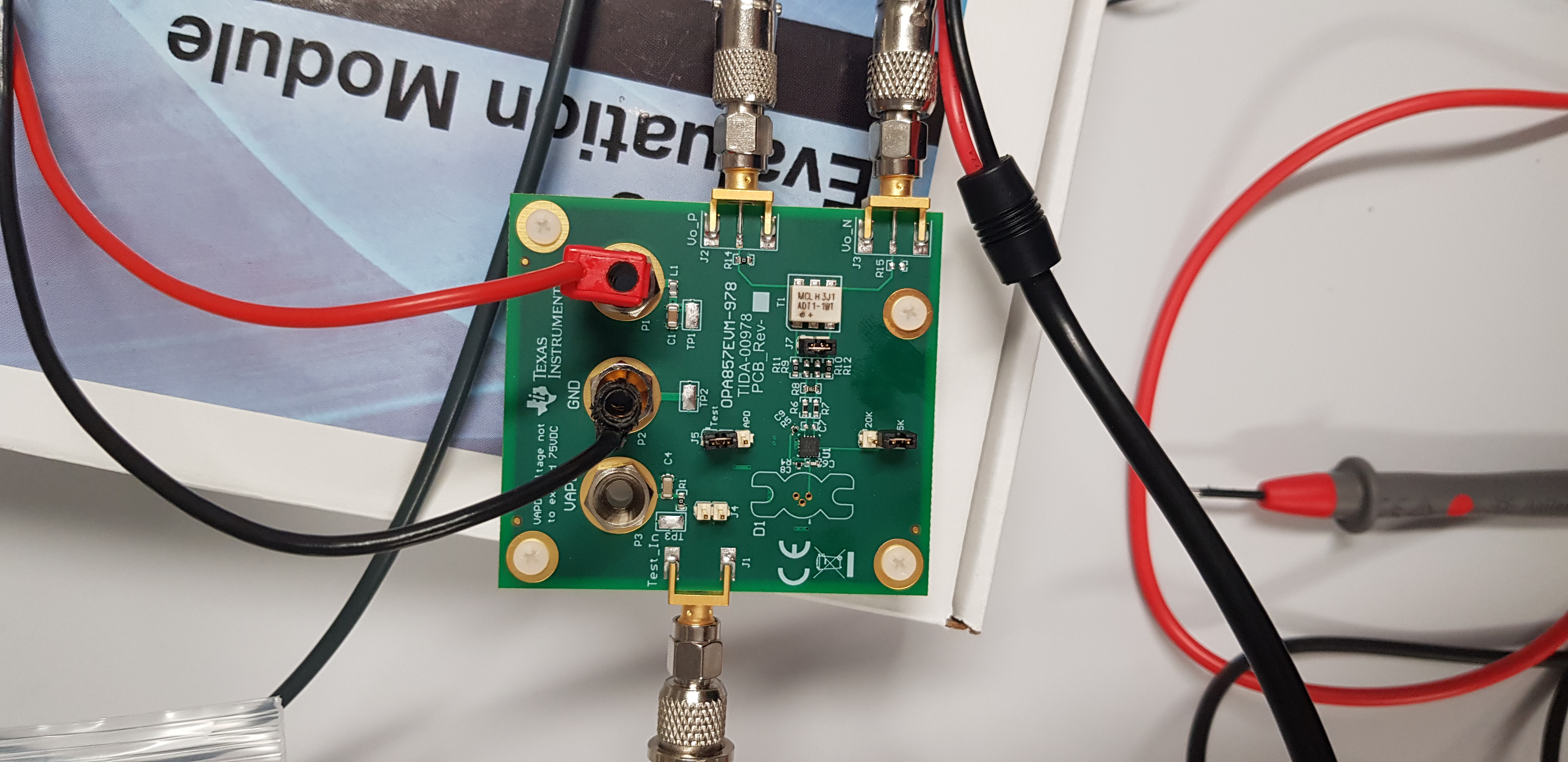
The instructions aren't clear on setting the module into Test Mode and do not give an indication of HOW an input voltage relates to a signal frequency of a photodiode. I have attempted to set it into Test Mode by:
1) Setting the +VCC banana jack to 3.3V
2) Setting the Test_SD to +VCC by use of the pins covers provided.
3) Connected a DC bias of 2.3V to the J1 Test_In SMA connector with the use of a BNA to SMA adapter.
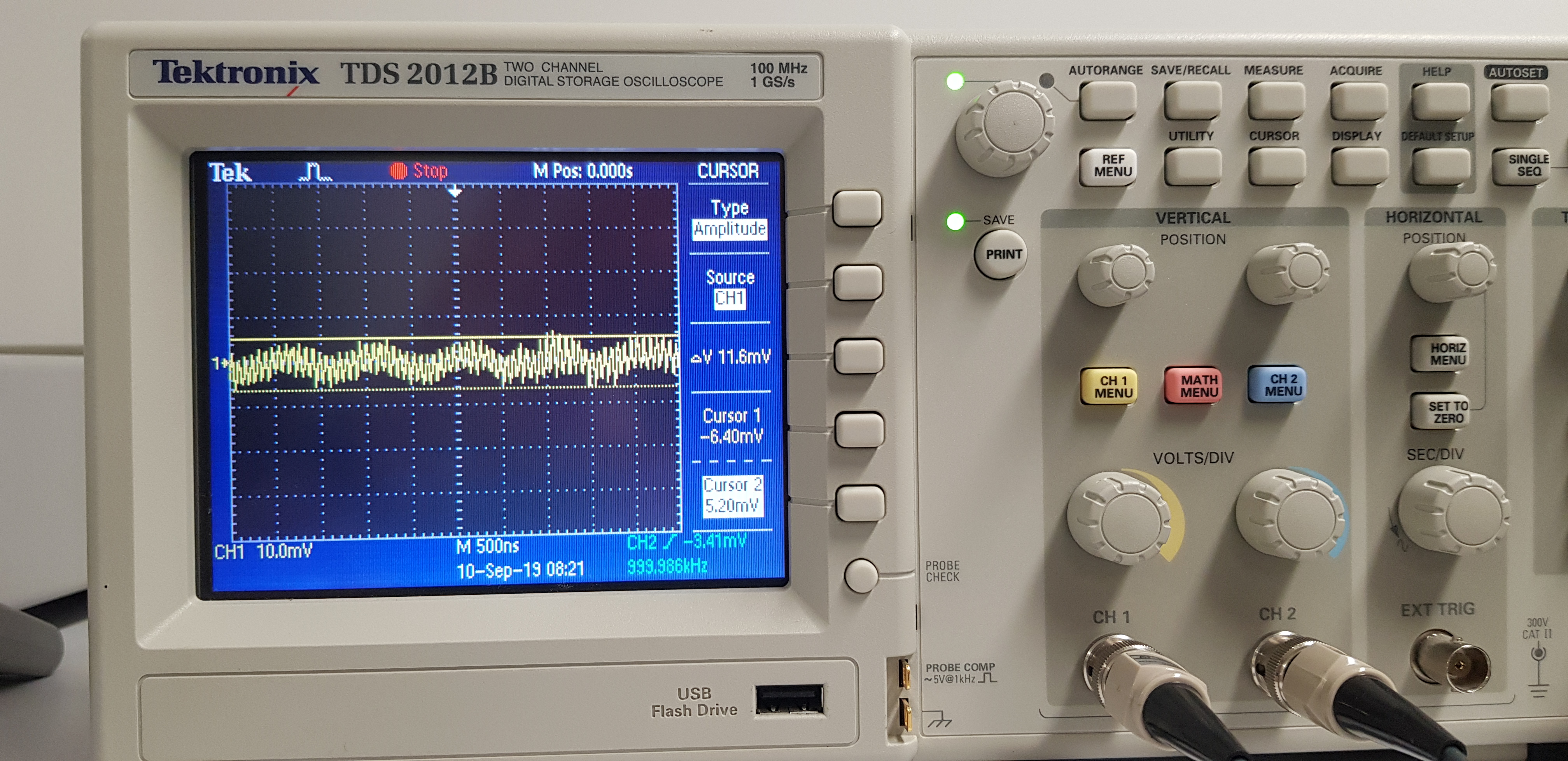
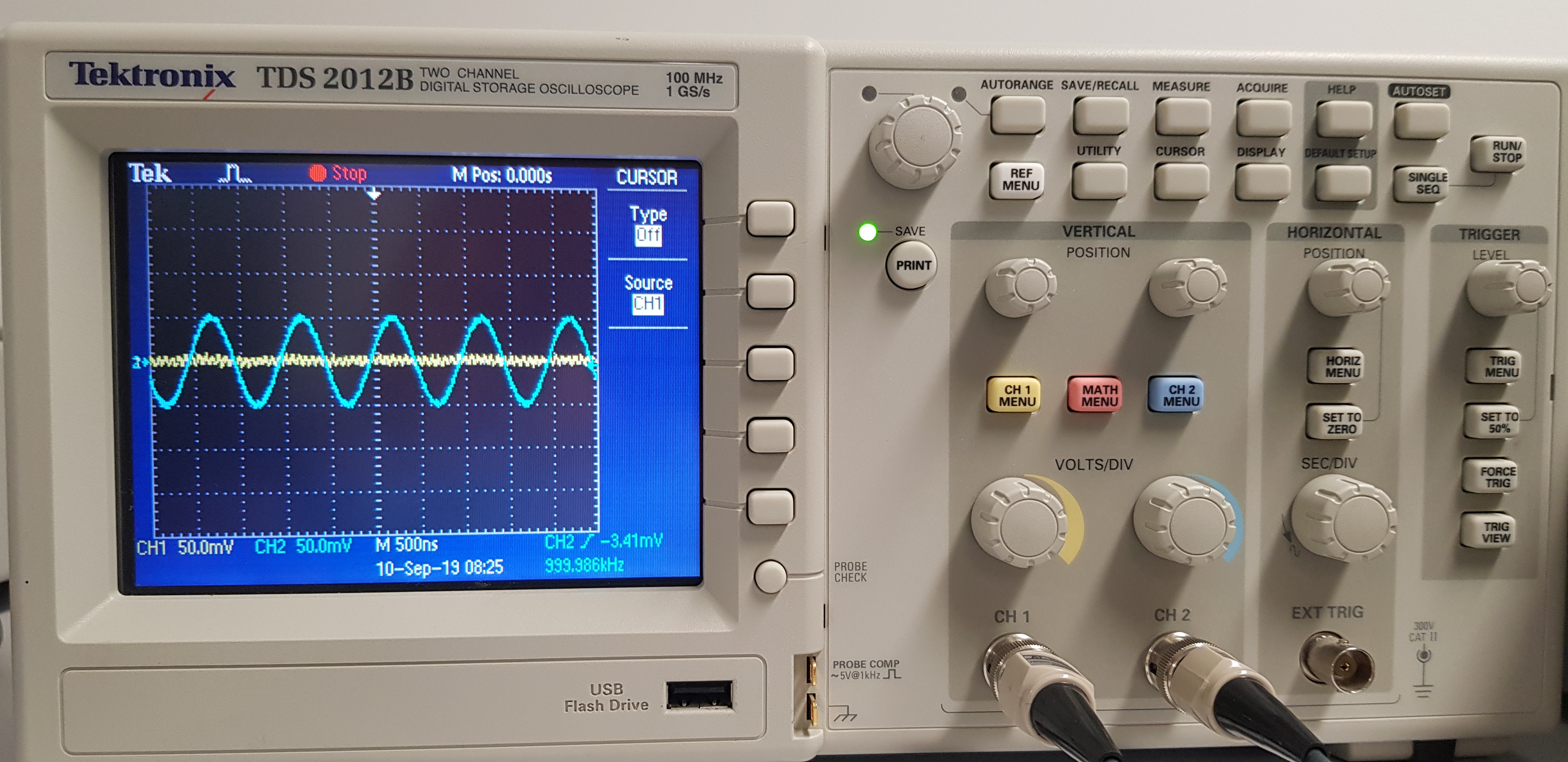
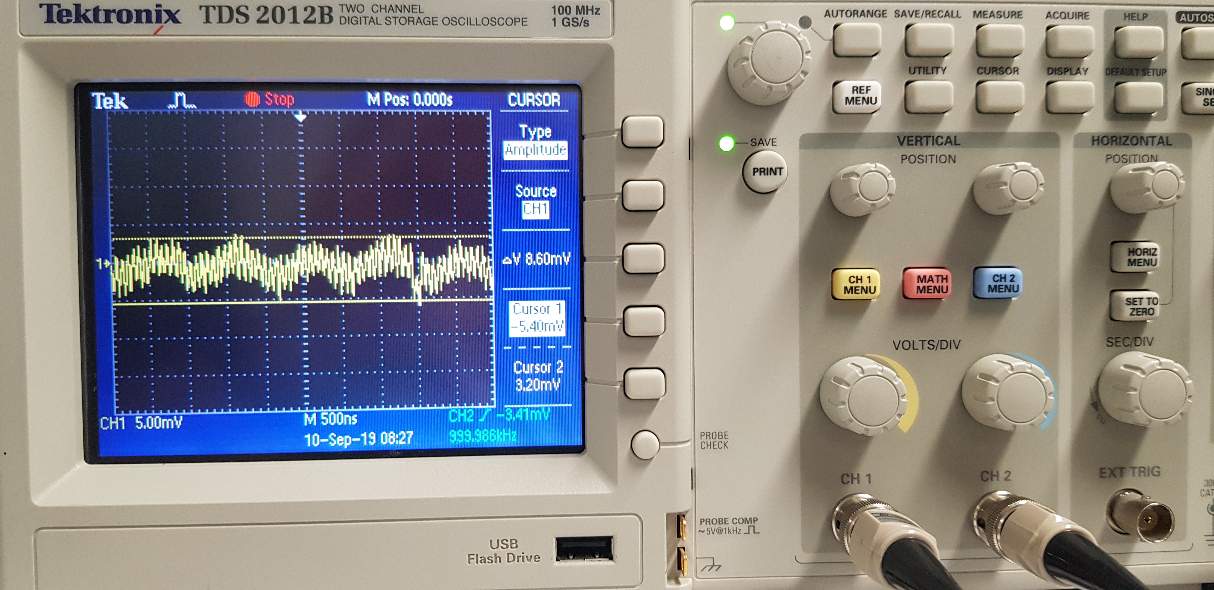
4) Monitoring the output via another SMA to BNA adaptor to an oscilloscope.

Assistance will be appreciated, as a step by step instruction to make sure I am operating it correctly. I get NO visible on the oscilloscope.