This thread has been locked.

If you have a related question, please click the "Ask a related question" button in the top right corner. The newly created question will be automatically linked to this question.

TLV7031: Noninverting Comparator With Hysteresis for TLV703x

Part Number: TLV7031
Other Parts Discussed in Thread: LM7332, TLV7011

Hi Team,

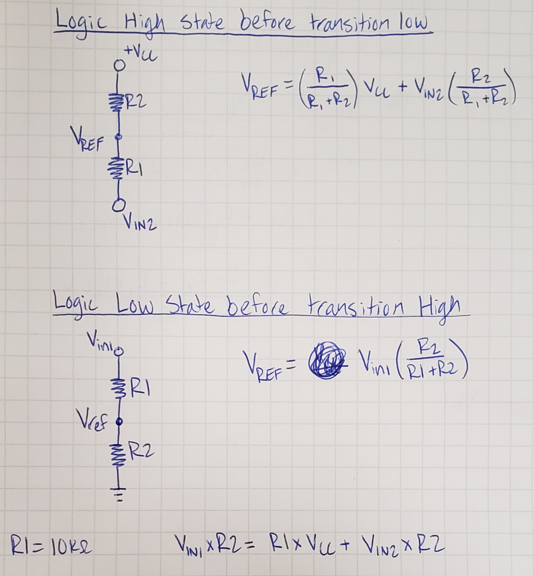
I tried to design a non-inverting comparator using TLV7031. My Vh is 3V and Vl is 2.4V and Hysteresis is 600mv.

Let me explain how I approach the problem. From the datasheet, Hysteresis is given in equation no (6). I know my hysteresis so I fixed R1 and I found R2.

Put this value of R1 and R2 in eq (4) to find my Vref. May I know the approach is correct or not.

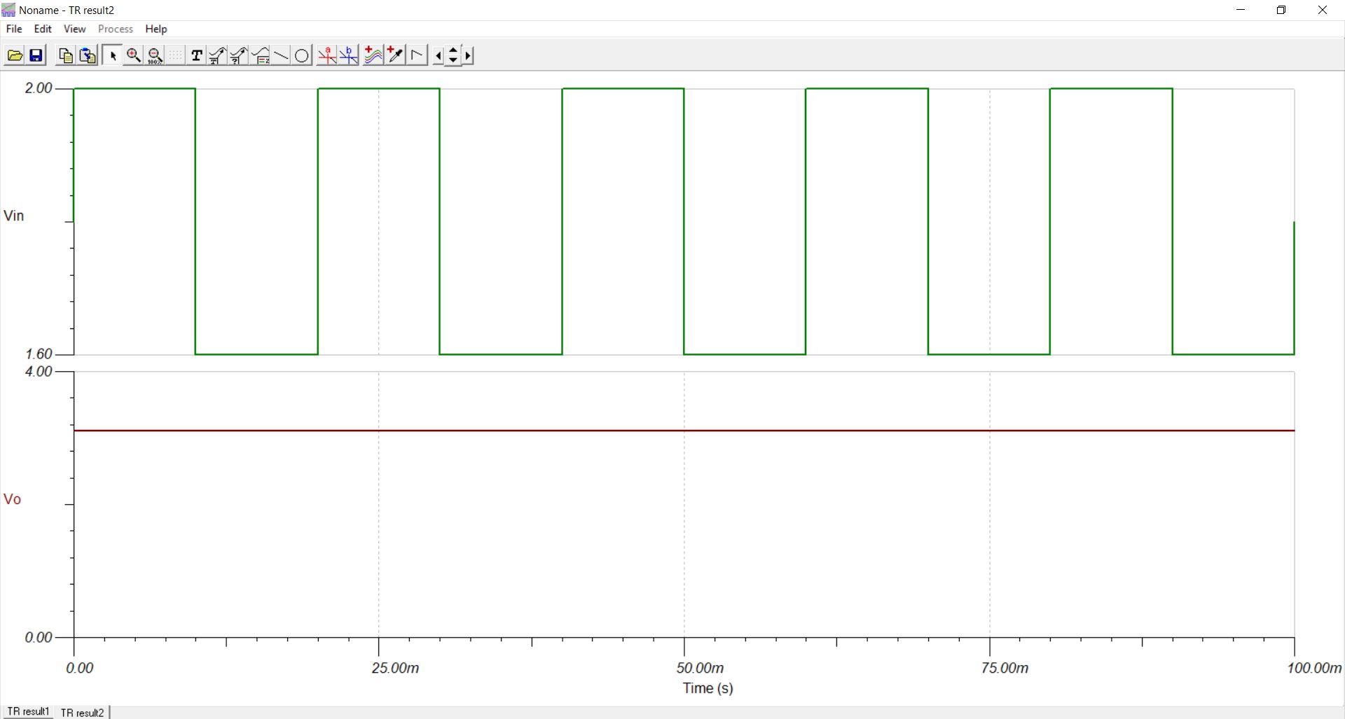
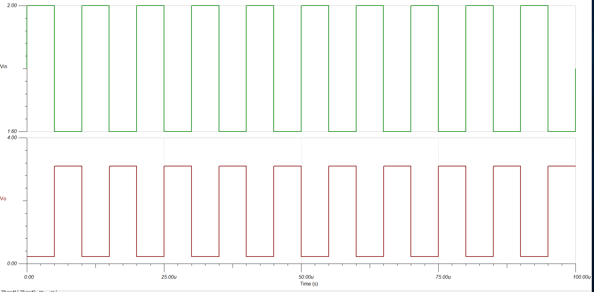
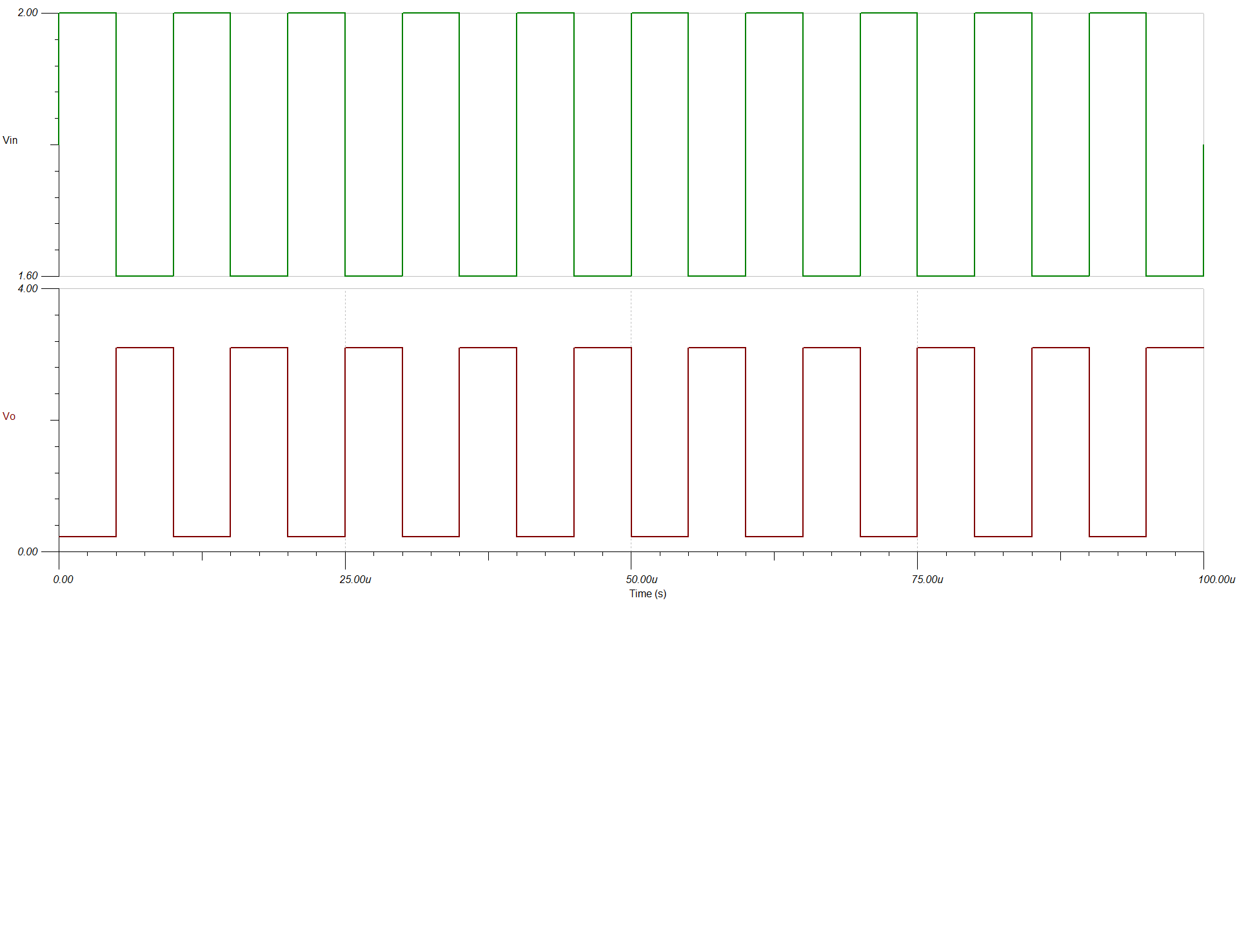
According to my simulation results are not proper .

http://www.ti.com/lit/ds/symlink/tlv7031.pdfNPM.TSCPlease find the attached simulation file.

Regards

Hari

  • Hi Hari,

    The equation you used to find R2 by fixing R1 was derived from equations 4 and 5. Therefore, I think you should start by using equations 4 and 5 and solve for the same variable in both. In other words, use the two independent equations provided (equations 4 and 5) to do these steps:

    1. Solve for both equations in terms of one variable.
      1. In the attached example it was Vref.
      2. The options are
      1. Vref
      2. R1
      3. R2
    • Set the two equations equal and assume one of the two remaining unknowns.
      1. In the example, I assumed R1 to be 10k.
    • Solve for the variable after making this assumption.
      1. In my case I would solve for R2
        1. The result for R2 agreed with your 55k.
    • Plug in the assumed value and solved value into one of the equations to solve for the third unknown.
      1. For my example, I solved for the Vref at the end by using equation 4 in the datasheet and got 2.538V for Vref.

    By approaching the problem this way, you only make one assumption and solve for three unknowns with two equations.

    I have also attached the TINA file with thresholds of 2.4V and 3.0V exactly when using the transient simulation with the source I used. Also be aware that this simulation model has internal hysteresis and input offset. This is why the DC transfer characteristics will be off but these equations are ideal.

    Thanks,

    Joe

    NPM_revised.TSC

  • Hi Joe,

    Thank you very much.

    Regards

    Hari

  • Hi Joe,

    My my spec is .The reference of the comparator are placed in that range, in particular REFH=1.282, REFL=1.182 à meaning that the hysteresis is 100mV.

    Please see the attached simulation file for details of I/P.

    my I/P and O/P looks same .May I know whyLPM_revised - Copy.TSC

  • Hi Hari,

    I would check how you calculated your reference voltage for the comparator. When I calculated it using the equation I provided for Vref, I got a 1.244V reference for the comparator instead of the 900mV source you had placed there. When using the 1.244V source, the comparator hysteresis thresholds are illustrated by the image below. They are approximately the thresholds you wanted of 1.282 and 1.182. 

    I think this is the response you were looking for in the comparator. I have attached a circuit with the reference of the comparator changed to 1.244V.

    Regards,

    Joe

    LPM_revised_2.TSC

  • Hi Hari, 

    I think I misinterpreted your question. I think you want the thresholds from the input of the buffer to the output of the comparator to be 1.282 and 1.182.

    For this to be accomplished, I used a 875mV reference for the comparator and an R4 of 473k. I've attached the circuit with these thresholds from input to the LM7332 to the output of the TLV. Sorry about the confusion.

    Regards,

    Joe

    LPM_revised_3.TSC

  • Hi Joe,

    Thank you very much.I simulated this circuit .My output looks weird.Please fine the attached result.

    O/P is always high

    Regards

    Hari

  • Hi Joe,

    Please ignore the previous email.When I changed the reference vlaue it is working fine.

    but when i changed the I/P frequency to 100Khz I can see a phase shift in I/P and O/P.may I know why 

  • Hi Hari,

    Can you send me your TINA file and what is your input range? Knowing the range for your inputs will help me better understand the thresholds you want to set. I was under the impression that you want the comparator to output HIGH when VG1 is 1.282 and the comparator to output LOW when VG1 is 1.182. 

    Thanks,

    Joe

  • Hi Joe,

    Sending the simulation file along with this email.  What I observed is that at high frequency Let us say 100Khz the there is a 180-degree phase shift between input and output.

    Regards

    Hari

    LPM_revised .TSC

  • Hari

    you are simulating with a very slow comparator (nanopower) which has considerable propagation delay (usec).  If you need to operate with a 100kHz input I suggest you switch to the TLV7011 which is approximately 10x faster.  You should see considerably less phase error when using this device.

    Chuck

  • Hari,

    I found that the part was modeled with a 5us delay which was why you were getting a 180 degree phase shift on a 10us input signal. I changed the model to have a 3us typical prop delay as shown in the datasheet.

    Attached is your fixed schematic.

    Regards,

    JonnyLPM_revised.TSC

  • HI Chuck,

    Sorry for the delay in reply.

    TLV7011 is working fine for me.

    Regards

    Hari

  • Hi Joan,

    Thank you very much.

    It is working fine now.Thank you for your support.

    Regards

    Hari