This thread has been locked.

If you have a related question, please click the "Ask a related question" button in the top right corner. The newly created question will be automatically linked to this question.

OPA820: Design Methodology for MFB Filters

Part Number: OPA820
Other Parts Discussed in Thread: OPA317

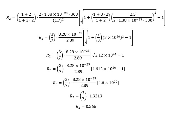
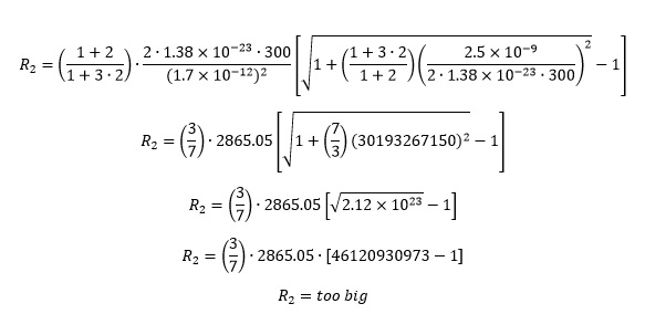
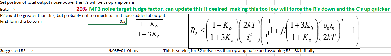
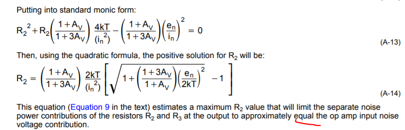
Hello, I'm using the document "www.ti.com/lit/an/sboa114/sboa114.pdf" "Design Methodology for MFB Filters in ADC Interface" to design a 2nd order Low-pass filter with a gain of 1 and Fc = 15KHz. I'm looking at the example on page 8 and have a question about the calculation of R2. The document says that R2 is calculated by Equation 9 on page 4. I don't know what the term 2kT is and would like ask someone for help.

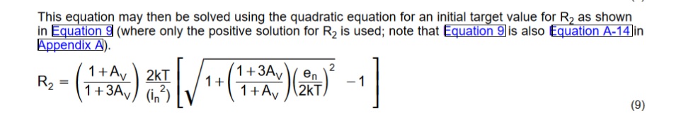
The in and en are from the datasheet of the OPA820, am I correct?

If anyone can help me I would be very thankful.

Respectfully,

Joe

  • Hi Joe, 

    "k" represents Boltzmann's constant, which is euqal to 1.38064852 × 10⁻²³ (m2 kg s-2 K-1). It has to do with the energy of particles and is an important part of noise calculations for resistors in electronics. 

    "T" represents the temperature in Kelvin. Typically we just use room temperature, but if you know your circuits ambient temperature that will be more accurate. 

    "in" is the input current noise and "en" is the input voltage noise of the device and can be found in a datasheet. Occasionally you might come across a device that doesn't list a current noise. In that case you can just assume it is irrelevantly small, like 1 fA/rtHz. 

    Regards, 

  • Hey Joe, 

    THe OPA820 is massive overkill for a 15kHz filter, 

    With GBP adjust on the RC's I am showing you only need 316kHz GBP to hold 20dB min LG. You could probably do this comfortably with a 1Mhz GBP op amp. You did not give the Q, but here is an RC solution for a Butterworth, Q=0.707

    This design hit the maximum C of 33nF in low cost C0G, that scaled the R's up a bit more than a low noise design would do. This optimization minimizes the Fo and Q fit error using E96 R's. It does let the gain go off one standard value if that is the best Fo and Q fit. 

  • Jacob,

    Hello, thank you very much for responding to my post. I entered the numbers into Equation 9 to calculate R2 but I don't get the same answer as the document.

    Would you be so kind to look over what I have an help me find my error?

    R2_Calc.docx

    Thank you,

    Joe

  • Michael,

    Hello, thank you very much for responding to my message. I am not an "Analog" guru but I am enjoying learning things that I didn't get in school. Quick question for you, how did you calculate the GBP? What is "LG" Thank you for suggesting a Q value. What is C0G and E96?

    The spreadsheet tool you used looks very handy, is that available to the public?

    Thank you,

    Joe

  • Where is that 300 coming from, there are no R's in the equation and, 

    Your 1.7 needs to be 1.7e-12 and your 2.5 needs to be 2.5e-9

    Keep in mind this is an approximate limit simply to scale the R's into a range where they do not dominate the noise over the op amp terms themselves. Other limits come into play as well where this full flow is kind of bouncing against different considerations trying to compromise a number of things (noise, I/O loading, C range, noise gain peaking, etc.) 

  • Incidentally, that equation for the OPA820 is calculating 90.8ohms, but, I had set a min input R3 of 402ohms so that is going to override and scale R2 and R3 up. 

    And as it iterates to a useable C solution, I limit the max C to 33nF which raised the R's even more. So the equation is useful sometimes as a starting point, but often not in the final solution due to other considerations. 

  • hey Joe, no that spreadsheet is the result of many years of iterating on this from that original app note (which, incidentally had errors in the cubic coefficient expressions that I fixed in a later article - but you not going that far into it - and you don't need to if the GBP is high enough) and not publicly available - and I am changing it minutely all the time. I do deliver designs out of it all the time. The full solution spreadsheet is about 12 sheets long and passing coefficients to a cubic solver that is a seperately running spreadsheet. 

    GBP - gain bandwidth product, this is the true on pole open loop gain intersection with 0dB - often incorrect in datasheets

    LG loop gain, difference between the Aol curve and the Noise gain curve - that is described in the app note, 

    C0G is a low tempco dielectric preferred for active filters - above 33nF they increase in cost quickly

    E96 is standard 1% R values - you can only implement with standard values so you might as well pick those that give the best nominal fit. 

  • Hello, the 300 is the Temperature in Kelvins. Is this not correct?

  • Here's another attempt. Still not right. I must be missing something:

    0435.R2_Calc.docx

    "in" that is squared right?

    Joe

  • Actually, there might be a typo in that equation, if I look at what is in my spreadsheet there is this beta term which is the % of total output noise power attributed to the resistors - I have that set to 20% in the solution tool, 

  • So actually going into that Appendix A, that was assuming beta =1 as indicated by the equal comment, I guess later made that a scaling term beta to target < equal noise power contributions,

  • Michael,

    Hello, was I correct in using T of 300 Kelvins? Did you see any errors in my calculations? Sure would be nice to see where I'm getting the wrong R2 value. 

    Respectfully,

    Joe

  • hey Joe, I did a little more work on this with your OPA820 gain of 1 design, The attached spreadsheet breaks the calculation into pieces and step by step works towards the result - I get 76 ohms now.

    I tried that in sim for the OPA820, and the output noise increases from 2*2.5=5nV for just the op amp to 6nV using all 76ohm R's. So I guess the beta might be % increase in spot noise. Been a long time since I worked on this, it is easy to get messed up on executing that equation. And we don't use it in this case anyway the loading would be too much and the caps too large. 

    Max R2 calculation by noise.xlsx

    I did a couple of tests here with simulation to see if equation is working, yes it does. Makes me feel better, was supposing I had an error in the original for a while. This did expose a model error in the OPA317 noise - it is 45nV in the model, datasheet is 55nV. 

    Testing the max resistor equation in an MFB for noise increase.docx

  • Michael, Hello, thank you very much for getting back to my post. Can you try changing the Ko term to 2. The spreadsheet doesn't give an R2 value near 336.38 as indicated on page 8 of the "Design Methodology" document. I get 75.7 ohms. What am I missing? Respectfully, Joe
  • Hey Joe,

    As Micheal mentioned in a previous response the main difference between the spreadsheet and "Design Methodology" document is the Beta factor term. The document assumes a Beta factor of 1, while the spreadsheet uses a 0.2 beta factor. By updating Micheal's spreadsheet to use a beta factor of 1, a value of 347 ohms is achieved.

    Best,

    Hasan Babiker

  • Now I got it! Thank you very much. Joe