This thread has been locked.

If you have a related question, please click the "Ask a related question" button in the top right corner. The newly created question will be automatically linked to this question.

INA186: Amplifier for LS impedance sensing

Part Number: INA186
Other Parts Discussed in Thread: PCM1861, INA190, , INA190EVM, INA132, INA240, OPA2192, INA240EVM, OPA192, THS4131, INA826, INA821, INA194, THS4551, INA149

For a loudspeaker sense application I need to amplify a small differential signal which is superposed on a large common signal.

I tried first with a current sense amplifier, but the signal to noise is very small. Which makes it impossible to use with for very small differential signal.

Then I tried with an opamp a large common mode input range (rail-to-rail at input). This works rather well for the differential signal, but from the moment the common mode signal becomes too high, my amplified differential signal starts having deformation. I still work within the specified common mode input voltage range.


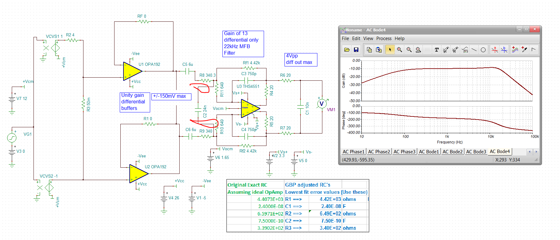
The circuit drawn of what I intend to realize is attached at the bottom.

The ADC that I use is the PCM1861 (low noise ADC).

Getting the sense resistor voltage direct into the ADC differential input is not OK because there is worst case 73dB between common mode and differential mode signal. Common mode rejection ratio is 56dB for the PCM1861. So differential voltage won’t be measurable.


With the current sense amplifier, I had the issue that I could only get 58dB STN with the 4A and with 0.08A I only got about 18dB STN. I’m not sure whether it was the voltage noise density specification which was too high or the CMRR was too low (was only 100dB).


For low noise I chose not to go for another current sense amplifier but instead for a low noise opamp with rail-to-rail input. But now even with staying within voltage input specs, I have at low common mode voltage at the input pins that I get deformation at my amplified differential signal.


What opamp would you suggest?

I was thinking to try on the INA186A1 or the INA 190A1 which has higher CMRR specs but again current sense amplifier. But a current sense amplifier doesn't have good noise specifications.

For a low noise amplifier with high common mode input voltage I find it difficult on the TI website to get the amplifiers with wide Common mode capabilities or even with common mode capabilities beyond the supply voltage.

  • Hey Bart,

    Welcome to the E2E forum and thank you for your question.

    I am not quite following some of your signal-to-noise calculations. For INA190A1 I calculate 31dB at 0.08A load.

    En_rms = en_BB*SQRT(Kn*BW) = 75nV/rtHz * SQRT(1.22*45kHz) = 17.5uVrms

    En_pk-pk = 17.5uV * 6 = 105.4uVpp

    SNR = 20*LOG(4mV/105.4uV) = 31 dB.

    The fact that the VCM can swing 24Vpp at 20kHz is not a recommended use of the INA190. Even though the AC CMRR shows 100dB at 20kHz, yielding 10uV offset for 24V swing, the device was not designed for this purpose. The 100dB of CMRR might not be reliable since the AC CMRR is testing with VCM swinging closer to 1V, not 24V. You can always try it with the INA190EVM. Keep in mind that the INA186 is almost the same as the INA190, but different package and slightly less strict specifications.

    The INA240 might be the best current sense amplifier to use here, but traditionally I would say that this application has been better suited for difference or instrumentation amplifiers, which will have better noise and distortion spec. Maybe the INA132 could be a good starting point if you go this route.

    Hope this helps,

    Peter Iliya

  • Hi Peter,

    Thank you for your response.

    I follow your calculation, but on my board I've less good SNR than what you calculated. I didn't used yet the INA190, but another one, but similar voltage noise density spec. Due to this difference between calculated value and measured value, I started my question on the forum.

    I understand that the current sense amplifier wouldn't be the best choice. But when I look on the website of TI I cannot filter on difference or instrumentation amplifier with high common mode specifications.

    I don't understand also your proposal of the INA132. This is an old amplifier with still relatively high noise value and the CMRR is not low. I would rather think of a lower noise OPAMP and higher CMRR specification.

    Any idea how I could be able to filter on the catalog of TI on large common input voltage OPAMPs?

    Thanks in advance for your answer.

    Best regards,

    Bart Vercoutter

  • Hey Bart, 

    Here is a different approach to consider - buffering that V across the sense resistor with high CM and CMRR is no problem with the OPA2192.

    From there, you can strip off the CM voltage with AC coupling and center up on the ADC inputs with an FDA. That ADC offers diff input - maybe should use it. 

    Discussion and example TINA file, 

    Current sense solution.docx

    OPA192 buffered with THS4551 FDA with MFB.TSC

  • Hey Bart,

    I got the INA132 difference amplifier from narrowing down the search filters based upon your parameters. This device will not work for your system for a variety of reasons, but the basic reason is that you are trying measure current on a rail that varies from 0.6V to 24V with a supply voltage (VS) of 3.3V.

    Now usually a current sense amplifier (CSA) is perfect for this because they usually include input bias stages that allow part to operate with VS independent of VCM. The problem here is that the VCM can move at 20kHz and this is not usually a mode of operation we recommend with CSAs as you will create dynamic offsets due to AC CMRR, which we test with amplitudes closer to 1Vpp, not 23.4Vpp. I think it is still worth testing with the INA240EVM or INA190EVM. If the noise is too high on the output, then you could condition it with another filter using an op-amp that is powered off the same 3.3V supply. This would remove need for other supply voltage rails.

    With most other amplifiers (instrumentation, difference, operational) you will need voltage rails of at least 24V in order for these devices to work on a rail that reaches 24V. This is why you can’t explore “large common input voltage OPAMPs” because they don’t exist. The best you can get with any op amp is a rail-rail input and that simply means the VCM can be very close the V+ and V- voltage supply rails. Even with this the performance will degrade as VCM approaches the rail voltages. The OPA192 solution from Michael below uses rails of 26V and -5V to achieve optimum performance.

    You could maybe look into using large input resistors to protect the OPA inputs once VCM > V+, but I am not an expert on this. Another option is to use resistor dividers on the input pins to divide down the VCM below 3.3V, but this will increase noise and gain error possibly. This could easily be simulated.

    If you want to explore what possible instrumentation amplifiers will work one nice tool is the “VCM vs, VOUT plot generator”. See link below. This tool allows you to determine what output swing is possible given the range of VCM and supply voltages for all of our instrumentation amplifiers.

    http://www.ti.com/tool/INA-CMV-CALC

    All of our product search pages have filters on the left so you can narrow down and sort parts with the best CMRR.

    http://www.ti.com/amplifier-circuit/op-amps/general-purpose/products.html&sort=p4typ;desc

    http://www.ti.com/amplifier-circuit/difference/products.html#p358min=1.8;3.3&p1169max=24;500

    Sincerely,

    Peter

  • Hello Peter and Michael,

    Thanks for your replies.

    I'm waiting on some ordered components to test your proposed solutions. I'll continue on both ideas. Either working with current sense amplifier (INA240, INA186 and INA190 ordered). And on the other hand using differential amplifier (THS4131 ordered). But i'm less in favor of the last solution, because for full range operation, I need to create extra supplies, but I'll try with 0 to 24V supply also.

    Then I ordered also some instrumentation amplifier: INA826 and INA821 to test. And also the INA194 differential amplifier with integrated internal resistors. For the others I've also ordered pairs of matched resistors.

    Once I have results I'll come back to you.

    Best regards,

    Bart Vercoutter

  • Hello Bart, 

    Yes, the THS4131 can give a DC coupled CM level shift from your total range, but does require more supplies. Can you not use AC coupling and the simpler THS4551 solution I showed? 

  • Hello Michael,

    I'm not able to simulate it from your file, because it is made in TINA version 11. I can only download version 9.

    But I've build it myself with the values that I find on the schematic in the word document. I only replaced the THS4551 by the THS4131, because the first one is not yet in TINA V9, but for now I saw no issue in this. I was mainly doubting that the CM AC would be removed after the capacitors C5 and C6. This CM AC signal gets also to the input pins of the differential amplifier. And the CM AC signal is out of the supply range of the THS4551.  In my simulation it results in clipping the differential output signal of the differential  amplifier is clipping to its rails.

    I'm also affraid with the amount of resistors that are used around the THS4551. They all needs to be matched. It will not be easy to find exact values in matched resistors and it won't be easy also to rout it on the PCB.

    Best regards,

    Bart Vercoutter

  • I imported the THS4551 into TINA and rerun the simulation, but also with this one the input nodes of the opamp are going out of the supply range.

    I insert my simulation here belowAC-coupled.TSC

  • There are bunch of mistakes in your circuit - the input cap is not in the right place for an MFB - can't operate 8V supply on a 5.5V max part, 

    Here is my file saved as a V9

    3823.OPA192 buffered with THS4551 FDA with MFB.TSC

  • And actually, I had that cap in the wrong place in my file - sorry, moved it here - starting to imbalance input R for a CMRR sim too. 

    UPdated file,

    8666.OPA192 buffered with THS4551 FDA with MFB.TSC

  • Ok, input CM rejection sim with +/-0.1% on the Rg R's, need to add that in the opposite sense to the Rf as  well, abou 55dB reject midband. 

    Now keep in mind the INA CMRR is freqeuncy dependent, So the INA132 suggested earlier looks like this over F. And this is typ, not toleranced out - 

  • My simulator had an issue while simulating with your previous file. He gave the error "Convergence problem. Check the analysis parameters!" when performing the transient analysis. The last file was a TINA V11 file which I couldn't open.

    From the TINA V9 file. I saw that the amplitude that you use is 6V. I always simulate with theoretic maximum level 12V. To be correct, it can only be 11.4V.

    I changed the supply voltage and the capacitor location, but still is the common mode AC signal at the + and - input of the THS4551 beyond the supply rails.

    The signal VF1 shows the - input of the opamp. The signal VF2 is the signal at the + output of the opamp. VM1 is the differential output, VM2 is the signal of the generators.

    Here also the TINA file that I use:

    6431.AC-coupled.TSC

    Best regards,

    Bart Vercoutter

  • Have you looked at the INA149?

  • I've tested the different solutions.

    The instrumentation ampllifier INA826 gives the best result. About 36dB between signal that I have to measure (minimum current) and the CM AC induced signal. STN is about 48dB. I have to supply it on 24V and I have to foresee a mid supply.

    The next one is the current sense amplifier INA240. This one gives me 33dB between signal and CM AC signal. STN about 41dB. No extra's are needed. Because it is fed on 3V3 like the ADC, I can use the mid supply from the ADC for reference. 

    The INA190 give just the wanted 30dB signal to CM AC and only 32dB STN. This one is not good enough here.

    The circuit with the THS4551 doesn't work. The output signal is clipping.

    Thanks for your support.